• Product
  • Suppliers
  • Manufacturers
  • Solutions
  • Free tools
  • Knowledges
  • Experts
  • Communities
Search


What is the purpose of connecting the primary winding of a step-up transformer in series with the main supply and the secondary winding in parallel?

Encyclopedia
Encyclopedia
Field: Encyclopedia
0
China

The situation where the primary winding of a booster transformer is connected in series with the main power supply and the secondary winding is connected in parallel with the main power supply is not common in practical applications, because this connection method usually does not bring the expected benefits and may introduce unnecessary complexity and potential risks. However, assuming that this configuration is for a specific function, we can explore its possible purpose and application scenarios.

Series primary winding for purpose

When the primary winding of the booster transformer is connected to the main power supply in series, it means that the input end of the transformer is directly connected to the power line. This connection is usually intended to use the transformer as an impedance matching element or as a voltage regulator.

Purpose of parallel secondary winding

When the secondary winding of the booster transformer is in parallel with the main supply, it means that the voltage output by the secondary winding will be in parallel with the main supply voltage. This type of connection is usually used to provide a higher voltage output, and in some cases can be used to compensate for a lack of grid voltage.

Possible purpose

  • Voltage boost: If the grid voltage is lower than the required operating voltage, the voltage can be raised to the required level through a boost transformer. The secondary winding is in parallel with the main power supply to ensure that even in the case of grid voltage fluctuations, the load can get a stable high voltage.

  • Impedance matching: In some applications, it is necessary to match the impedance of the power supply to the impedance of the load to maximize power transfer efficiency. By connecting the primary windings in series, the impedance of the entire circuit can be adjusted.

  • Voltage regulation: The booster transformer can act as a voltage regulator to ensure that the voltage at both ends of the load is maintained at a constant level.

  • In the case of parallel connection, the booster transformer can supplement the shortage of grid voltage and ensure the voltage stability at both ends of the load.

  • Current limitation: In some cases, it may be necessary to limit the current through the load. By connecting the primary winding in series, it can play the role of current limiting. The parallel connection of the secondary windings ensures that the voltage at both ends of the load is not too affected by the current limitation.

Precautions in practical application

Although the above configuration may have some use in theory, there are several points to note in practical applications:

  • Safety:Placing the secondary winding in parallel with the main power supply can introduce safety hazards, especially if not properly designed, which can lead to short circuits or other dangerous conditions.

  • Efficiency: This configuration may not be the most efficient solution, as the loss and efficiency issues of the transformer need to be carefully considered.

  • Stability: A parallel connection may affect the stability of the system, especially if the grid voltage fluctuates.

More common ways to connect

In practical applications, it is more common to connect the primary winding of the booster transformer to the main power supply, while the secondary winding is directly connected to the load. This connection method can effectively increase the voltage, and is relatively simple and safe.

Sum up

The configuration of the primary winding of the booster transformer in series with the main power supply and the secondary winding in parallel with the main power supply can realize the functions of voltage boost, impedance matching, voltage regulation and current limitation in theory, but its safety and efficiency need to be carefully considered in practical applications. It is more common to connect the primary winding of the booster transformer directly to the main power supply and the secondary winding to the load. If you are considering this configuration in a specific application scenario, make sure that the design meets safety standards and has been thoroughly analyzed and tested.

Give a tip and encourage the author!
Recommended
Composition and Working Principle of Photovoltaic Power Generation Systems
Composition and Working Principle of Photovoltaic (PV) Power Generation SystemsA photovoltaic (PV) power generation system is primarily composed of PV modules, a controller, an inverter, batteries, and other accessories (batteries are not required for grid-connected systems). Based on whether it relies on the public power grid, PV systems are divided into off-grid and grid-connected types. Off-grid systems operate independently without relying on the utility grid. They are equipped with energy-s
Encyclopedia
10/09/2025
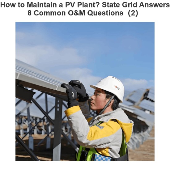
How to Maintain a PV Plant? State Grid Answers 8 Common O&M Questions(2)
1. On a scorching sunny day, do damaged vulnerable components need to be replaced immediately?Immediate replacement is not recommended. If replacement is necessary, it is advisable to do so in the early morning or late afternoon. You should contact the power station’s operation and maintenance (O&M) personnel promptly, and have professional staff go to the site for replacement.2. To prevent photovoltaic (PV) modules from being hit by heavy objects, can wire mesh protective screens be install
Encyclopedia
09/06/2025
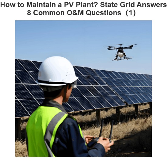
How to Maintain a PV Plant? State Grid Answers 8 Common O&M Questions(1)
1. What are the common faults of distributed photovoltaic (PV) power generation systems? What typical problems may occur in various components of the system?Common faults include inverters failing to operate or start due to voltage not reaching the startup set value, and low power generation caused by issues with PV modules or inverters. Typical problems that may occur in system components are burnout of junction boxes and local burnout of PV modules.2. How to handle common faults of distributed
Leon
09/06/2025
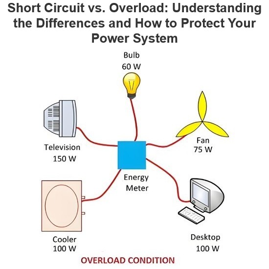
Short Circuit vs. Overload: Understanding the Differences and How to Protect Your Power System
One of the main differences between a short circuit and an overload is that a short circuit occurs due to a fault between conductors (line-to-line) or between a conductor and earth (line-to-ground), whereas an overload refers to a situation where equipment draws more current than its rated capacity from the power supply.Other key differences between the two are explained in the comparison chart below.The term "overload" typically refers to a condition in a circuit or connected device. A circuit
Edwiin
08/28/2025
Send inquiry
Download
Get the IEE Business Application
Use the IEE-Business app to find equipment, obtain solutions, connect with experts, and participate in industry collaboration anytime, anywhere—fully supporting the development of your power projects and business.