
Definition of Electrical Source
A source is a device that converts mechanical, chemical, thermal, or other forms of energy into electrical energy. As an active network element, it serves the purpose of generating electrical energy.
In electrical networks, the primary types of sources are voltage sources and current sources:
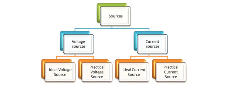
Current and voltage sources are further categorized into ideal sources and practical sources.
Voltage Source
A voltage source is a two-terminal device that maintains a constant voltage at any instant, independent of the current drawn from it. This is referred to as an Ideal Voltage Source, which features zero internal resistance.
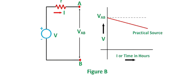
In practice, ideal voltage sources do not exist. Sources with inherent internal resistance are called Practical Voltage Sources. This internal resistance causes a voltage drop, reducing the terminal voltage. The smaller the internal resistance (r) of a voltage source, the closer its behavior aligns with an ideal source.
The symbolic representations of ideal and practical voltage sources are as follows:
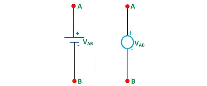
Figure A shown below shows the circuit diagram and characteristics of an ideal voltage source:
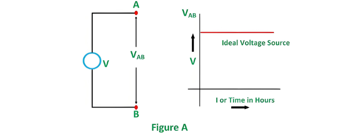
Figure B shown below gives the circuit diagram and characteristics of Practical Voltage Source:
Examples of Voltage Sources
Common examples of voltage sources include batteries and alternators.
Current Source
Current sources are similarly categorized into ideal and practical types.
Ideal Current Source
An ideal current source is a two-terminal circuit element that delivers a constant current to any load resistance connected across its terminals. Notably, the current supplied remains independent of the voltage across the source terminals, and it exhibits infinite internal resistance.
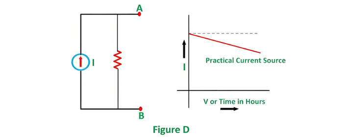
Practical Current Source
A practical current source is modeled as an ideal current source in parallel with a resistance. This parallel resistance accounts for real-world limitations, such as current leakage or internal losses. The symbolic representations are as follows:
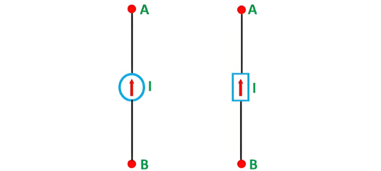
Figure C shown below, show its characteristics.
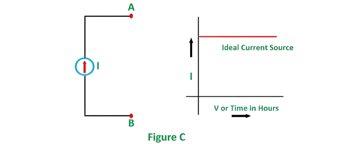
Figure D shown below shows the characteristics of Practical Current Source.
The example of current sources is photoelectric cells, collector currents of transistors.


