
Leading and lagging power factors are two key concepts related to the power factor in AC electrical systems. The main difference lies in the phase relationship between current and voltage: in a leading power factor, the current leads the voltage, whereas in a lagging power factor, the current lags behind the voltage. This behavior depends on the nature of the load in the circuit.
What is Power Factor?
Power factor is a crucial, dimensionless parameter in AC electrical systems, applicable to both single-phase and three-phase circuits. It is defined as the ratio of true (or real) power to apparent power.
In DC circuits, power can be determined directly by multiplying voltage and current readings. However, in AC circuits, this product yields apparent power, not the actual power consumed. This is because the total supplied power (apparent power) is not entirely utilized; the portion that performs useful work is called real power.
Simply put, power factor is the cosine of the phase angle between voltage (V) and current (I). For linear loads in AC circuits, the power factor ranges from -1 to 1. A value closer to 1 indicates a more efficient and stable system.
Definition of Leading Power Factor
A leading power factor occurs when a capacitive load is present in the circuit. In purely capacitive or resistive-capacitive (RC) loads, the current leads the supply voltage, resulting in a leading power factor.
Since power factor is the ratio of real power to apparent power—and for sinusoidal waveforms, the cosine of the phase angle between voltage and current—the leading current creates a positive phase angle, giving a leading power factor.
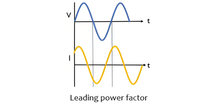
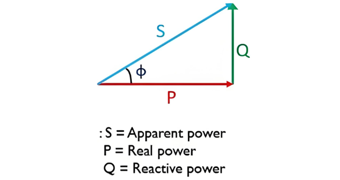
As evident from the figure above, the current I crosses the time axis at zero earlier in phase than the voltage V. This condition is known as a leading power factor. The figure below illustrates the power triangle for a leading power factor.

Definition of Lagging Power Factor
A lagging power factor in an AC circuit occurs when the load is inductive in nature. This is because, in the presence of a purely inductive or resistive-inductive load, a phase difference exists between voltage and current such that the current lags behind the voltage. As a result, the power factor of such circuits is said to be lagging.
Consider the waveforms of the supply voltage and the current through a purely inductive load:
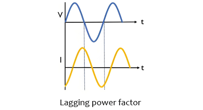
Here, the current crosses the zero point of the time axis at a later phase compared to the voltage, resulting in a lagging power factor. The power triangle for a lagging power factor is shown below:
Conclusion
From the above discussion, it can be concluded that ideally, voltage and current are assumed to be in phase, resulting in a phase angle of 0° between them. However, in practice, a phase difference exists, and this is represented by the power factor of the circuit.


