• Product
  • Suppliers
  • Manufacturers
  • Solutions
  • Free tools
  • Knowledges
  • Experts
  • Communities
Search


What aspects need attention during the installation of dry-type transformers?

James
Field: Electrical Operations
China

1 Pre - installation Preparation

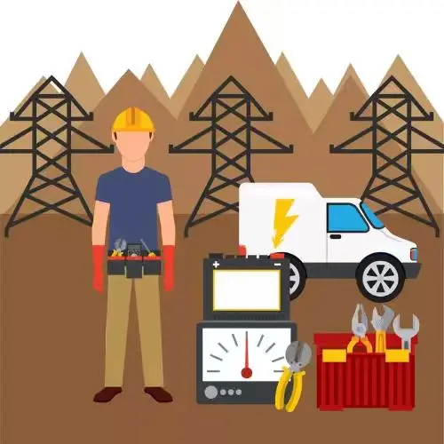
As a front - line installer, I know very well that the preparation work before installing a dry - type transformer must be thorough. First, I will carefully review the design drawings and technical documents, and check one by one the technical parameters such as the model specification, rated capacity, and voltage level of the transformer to ensure they are in full compliance with the design requirements. Then, I will conduct an unpacking inspection of the transformer body and accessories, focusing on checking whether the coils are deformed, the insulation is damaged, and whether the conductive parts are loose or oxidized. These details are directly related to the subsequent operation of the equipment. At the same time, check whether the random documents are complete, such as the factory test report, certificate of conformity, and instruction manual, none of which can be missing.

I also need to prepare the necessary construction tools and testing instruments, such as a megohmmeter (2500V), grounding resistance tester, phase sequence meter, and multimeter. These are the “weapons” to ensure accurate installation. In addition, a detailed construction organization design and safety technical measures must be formulated, clarifying the construction procedures, personnel division of labor, and safety precautions. Only in this way can the on - site construction be orderly, which is also the key to ensuring safe and efficient operations in my years of installation experience.

2 Foundation and Site Requirements

The installation of a dry - type transformer requires a stable and suitable foundation and site, which is the “cornerstone” for the long - term stable operation of the equipment. I have a deep understanding of this during on - site installation. To ensure the compliance of the installation site, I will use the standard inspection form for foundation bearing capacity and site dimensions (see Table 1) to check item by item, from the foundation strength to the site space, all must meet the requirements so that the subsequent operation of the transformer can be stable.

3 Transportation and Hoisting Requirements

Transportation and hoisting are key links in the installation of dry - type transformers, and I am particularly cautious every time I handle them. During transportation, anti - vibration and rain - proof measures must be taken, use special transport vehicles, and fix the transformer firmly to prevent it from shaking.

The hoisting equipment should be selected according to the weight of the transformer. Generally, the double - hook hoisting method is used, and the slings must pass the inspection. Before hoisting, I will repeatedly check the center - of - gravity position of the transformer and strictly install the slings according to the hoisting point positions marked on the nameplate. During the hoisting process, it must be slow and stable, and sudden lifting or braking is strictly prohibited, which is the bottom line for ensuring the safety of equipment and personnel. When in place, use a level to check the levelness, and the allowable deviation does not exceed 0.2%. Immediately after installation in place, fix the base to prevent displacement. In case of large - scale dry - type transformers exceeding 10t, a special hoisting plan must be prepared and hoisting verification carried out, and no carelessness is allowed.

4 Assembly Process and Steps

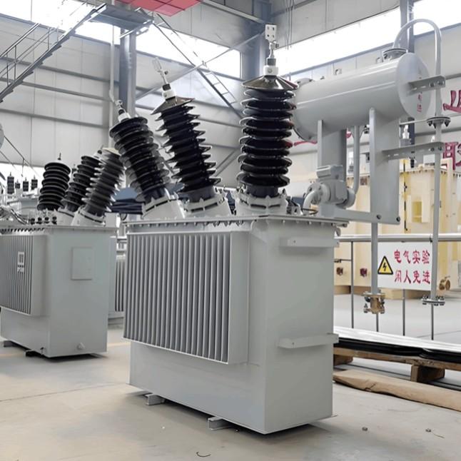
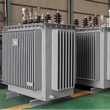
The assembly of dry - type transformers must be carried out in strict accordance with the process flow, and I dare not make a mistake at any step on site. First, install the base, adjust the level, and fasten the anchor bolts with a torque wrench, and the torque must be accurate. Then, place the transformer body in position, check whether the transformer body is vertical, and if not, adjust it carefully with gaskets.

When installing the high - and low - voltage side insulating bushings, the bushings must be vertical and the sealing must be good. Then install accessories such as temperature controllers and fans, and check whether the wiring is correct one by one. In case of transformers transported in separate parts, assemble them strictly according to the factory number sequence and not randomly. After assembly, conduct an appearance inspection to ensure that the components are installed firmly and the wiring is reliable. Finally, install the protective cover and stick warning signs at the specified positions. Only by doing these details well can the equipment operate reliably.

5 Wiring and Grounding Requirements

Wiring and grounding are directly related to the safe operation of the equipment, and I am extremely careful when doing this work. The wiring on the high - and low - voltage sides strictly complies with the design requirements, and the cross - section of the conductor must meet the current - carrying capacity. Generally, copper - core cables are selected. The high - voltage side connection uses heat - shrinkable or cold - shrinkable terminal heads, and the low - voltage side uses copper busbars for connection. The contact resistance of all connection points is less than 50μΩ, and anti - loosening devices are used for bolt connections.

The transformer must be provided with two independent grounding points, the grounding resistance shall not exceed 4Ω, and the grounding wire shall use a copper conductor with a cross - section of not less than 95mm². The neutral - point grounding method shall comply with system requirements, and the correct grounding resistance value shall be selected for the resistance grounding system. Control lines for auxiliary equipment such as temperature sensors and fans shall use shielded cables and be properly grounded. Only by adhering to these specifications can the safe operation of the equipment be ensured.

Give a tip and encourage the author!
Recommended
Mismatched AC Contactor Sizing? These 4 Typical Issues You Must Not Ignore – Click to View Solutions
AC contactors (with the electrical schematic code KM) are core electrical devices used to control the connection/disconnection between power supplies and loads in circuits, and they are also common equipment that electricians need to work with regularly. In practice, it is not uncommon to find that some peers make mistakes in selecting AC contactors, leading to improper sizing and subsequent persistent issues. Here, four of the most typical common mistakes are highlighted for reference.I. Over-R
James
09/11/2025
Proper Installation of AC Contactors | A Practical Guide to Avoid Burning and Misoperation, Master It in One Article
AC contactors are widely used for switching and controlling power circuits. They use main contacts to open and close circuits, and auxiliary contacts to execute control commands. Main contacts typically only have normally open contacts, while auxiliary contacts often have two pairs of contacts with normally open and normally closed functions. Small-sized contactors are also frequently used as intermediate relays to work with main circuits, thereby achieving the function of remote control or cont
James
09/11/2025
Technical Analysis of 220 kV High-Voltage Cable Construction in Winter
1.Work Environment Requirements and Safeguard MeasuresBased on technical requirements for cable equipment storage, laying, transportation, laying, transposition, testing, and cable terminations, the project owner and construction units have conducted extensive trials and implemented protective measures regarding ambient temperature, humidity, bending radius, traction control, and route optimization. These measures ensure high-voltage cable quality and on-site safety under harsh winter conditions
James
09/03/2025
Considerations and Recommendations for Flame-Retardant Selection of High-Voltage Cables
1.Flame-Retardant Cable Classification StandardsThe flame-retardant standard system is divided into two main categories. The first category follows the "Classification of Burning Behavior for Electric and Optical Fiber Cables" GB 31247. Cables complying with this standard system are widely used in densely populated areas such as high-speed railways and subways. This standard imposes strict requirements on parameters such as smoke density, heat release, and total smoke production, and cables typi
James
09/03/2025
Seed Inquiry
Download
Get the IEE Business Application
Use the IEE-Business app to find equipment, obtain solutions, connect with experts, and participate in industry collaboration anytime, anywhere—fully supporting the development of your power projects and business.