Medium-voltage current-limiting fuses are primarily used for protecting loads such as transformers and motors. A fuse is a device that, when the current exceeds a given value for a sufficiently long duration, interrupts the circuit in which it is inserted by melting one or more specially designed and proportioned components. Current-limiting fuses may have difficulty clearing intermediate current values (overloads between 6 to 10 times the rated current), so they are typically used in combination with switching devices.
Medium-voltage current-limiting fuses operate by inserting a metallic conductor (the fuse element) in series with the circuit. When an overload or short-circuit current passes through the element, the resulting self-heating causes it to melt once the current exceeds its rated value, thereby opening the circuit. Consequently, fuses have relatively high resistance, leading to significant heat generation under rated current. For example, a 125A fuse generates about 93W of heat, a 160A fuse generates 217W, and a 200A fuse produces 333W. In the market, 12kV fuses are available with current ratings up to 355A, resulting in even higher power dissipation.
In practical switchgear applications, the rated current of the fuse should be approximately 1.25 times the long-term operating current of the load. When fuses are installed within a three-phase enclosed cabinet or individually housed in insulated resin-encapsulated tubes, the confined space of the fuse compartment cannot dissipate heat effectively. Heat generation exceeding 100W may cause temperature rise to exceed acceptable limits, necessitating derating of the fuse capacity.
Moreover, due to size constraints in ring main units (RMUs), the fuse compartment diameter in compact gas-insulated RMUs is typically around 90 mm, allowing installation of fuses up to 160A (commonly used up to 125A). This limits protection to transformers up to approximately 1250 kVA. Transformers larger than 1250 kVA require protection via circuit breakers. Similarly, for F-C (fuse-contactor) circuits used to protect motors, the solution is generally limited to motors up to 1250 kW. Larger motors require circuit breaker-based control and protection.
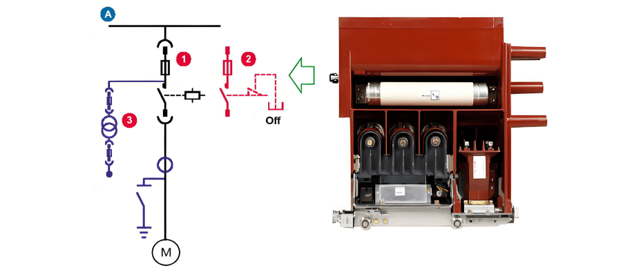
In motor control applications, the F-C combination employs a high-voltage current-limiting fuse as a backup protective device. In an F-C circuit, when the fault current is equal to or less than the breaking capacity of the vacuum contactor, the integrated protection relay should operate, causing the contactor to interrupt the current. The fuse operates only when the fault current exceeds the relay setting or if the vacuum contactor fails to operate.
Short-circuit protection is provided by the fuse. The fuse is typically selected with a higher rated current than the motor’s full-load current to withstand inrush currents during startup, but it cannot simultaneously provide overload protection. Therefore, inverse-time or definite-time relays are required to protect against overloads. Components such as contactors, current transformers, cables, the motor itself, and other circuit equipment may be damaged by prolonged overloads or by let-through energy exceeding their withstand capability.
Motor protection against overcurrents caused by overloads, single-phasing, rotor lock, or repeated starts is provided by inverse-time or definite-time relays, which operate the contactor. For phase-to-phase or phase-to-ground faults with currents below the contactor’s breaking capacity, protection is provided by the relay. For fault currents exceeding the contactor’s breaking capacity up to the maximum withstand level, protection is provided by the fuse.
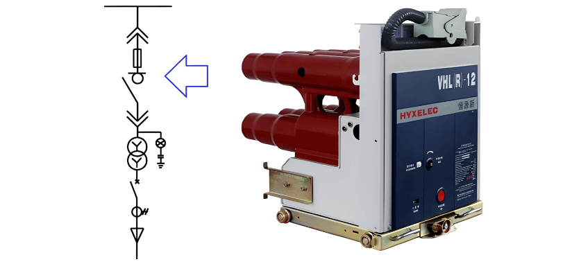
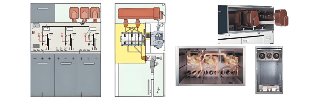
Fuse-combination switchgear is primarily used for transformer protection. Typical applications include transformer feeder circuits in ring main units (RMUs), where an SF6 load switch is combined with fuses to achieve a compact, maintenance-free design. Another configuration is the draw-out trolley solution, in which a fuse-load switch combination unit is integrated into a medium-voltage switchgear (e.g., metal-clad switchgear), enabling convenient withdrawal for maintenance and fuse replacement.
When combination appliances are used for transformer protection, a two-stage protection scheme is established by incorporating relay protection. For overload or moderate overcurrent conditions, the relay sends a trip command to the load switch to clear the fault. For severe short-circuit faults, the fuse operates and triggers the switch to trip, thereby interrupting the circuit.
When an internal fault such as a short circuit occurs in a transformer, the resulting arc decomposes the insulating oil into gas. As the fault continues, internal pressure increases rapidly, potentially leading to tank rupture or explosion. To prevent tank failure, the fault must be cleared within 20 milliseconds (ms). However, the total breaking time of a circuit breaker—composed of relay operating time, inherent tripping time, and arcing time—is typically no less than 60 ms, which is insufficient for effective transformer protection. In contrast, current-limiting fuses provide extremely fast fault interruption, capable of clearing faults within 10 ms, thus offering highly effective protection for the transformer.