Application Analysis of Load Switch and Current-Limiting Fuse Combination Apparatus

Echo
06/27/2025

As a front - line technician in loop - network power supply and prefabricated substation operation and maintenance, I deeply understand equipment iteration driven by high - voltage urban expansion. Per the National Power Supply and Consumption Regulations, for equipment over 250kW or 160kVA transmission capacity, 10(6)kV high - voltage power supply and 220/380V step - down form a necessary pattern, making loop - network units and prefabricated substations key in distribution networks.
I. Equipment Structure and Protection Scheme Selection
(I) Equipment Composition
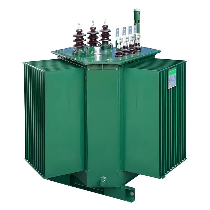
Loop - network units I handle usually have 2 loop cable intervals and 1 transformer circuit interval. Prefabricated substations integrate high - voltage switches, transformers, and low - voltage devices into compact, prefabricated sets for indoor/outdoor use. The core is high - voltage switches’ protection against transformer faults (e.g., short circuits).
(II) Protection Scheme Comparison
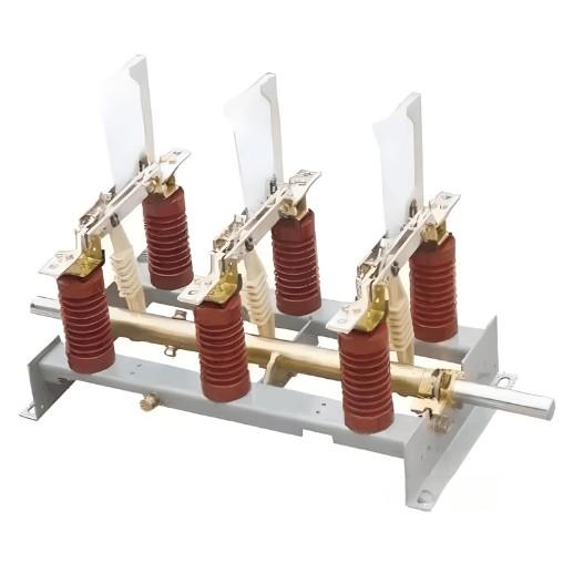
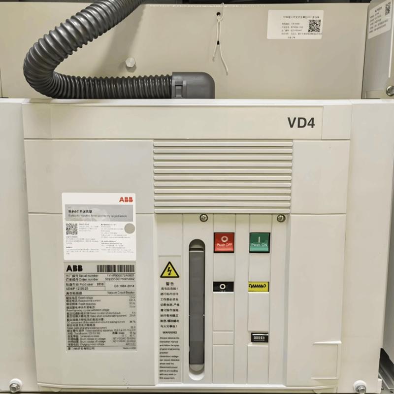
In practice, I tested two protection methods: circuit breaker and load switch + current - limiting fuse. The latter is superior —— simple, cost - effective, and more effective for transformers. Short - circuit tests show transformers need short - circuit clearing within 20ms to avoid tank explosions; current - limiting fuses do it in 10ms, while circuit breakers take ~60ms (relay + operation + arcing time), so I prefer the fuse scheme.
II. Necessity of Load Switch + Current - Limiting Fuse
(I) Application Advantages
Most domestic and foreign loop - network/prefabricated substation projects I participated in use load switch + current - limiting fuses. They feature simple structure, low cost, and good protection for transformers. Short - circuit tests (verified on - site) show fuses clear faults in 10ms (vs. circuit breakers’ ~60ms), critical for preventing tank explosions.
(II) Cooperative Logic
Fuses may cause unbalanced phase operation if single - phase fusing occurs. Thus, load switches must cooperate: fuse strikers trigger load switch tripping for three - phase breaking —— a verified, indispensable coordination.
III. Cooperation Key Points of Load Switch and Fuse
As a front - line worker, I know their cooperation is vital. The IEC420 standard defines rules, dividing current into 4 regions (my debugging basis):
(I) Region I (I < Iak)
Iak (combined appliance rated current) is less than fuse rated current Ia.nT (due to installation temperature/heat loss). Load switches break rated current and extinguish three - phase arcs —— my daily inspection focus.
(II) Region II (Ia.nT< I < 3Ia.nT)
In overload, fuses bear over - current first. At ~2Ia.nT, melts act (but not arc - extinguishing), strikers trigger load switches for three - phase breaking. I test this time - difference logic to avoid protection failure.
(III) Region III (Transfer Current ITC, ~3Ia.nT Start)
Fuses can extinguish arcs after action. One three - phase fuse acts first, triggering strikers; load switches extinguish other two - phase currents. The key is transfer current (load switch’s max breaking current at specific power factor, 5Ia.nT15Ia.nT), checked during selection/verification.
(IV) Region IV (Current - Limiting Range)
For extreme faults, fuses act in the first half - wave to limit fault current peaks; load switches act but don’t break current. I verify this logic in drills for proper operation.
IV. Transfer & Hand - over Current Requirements
These parameters ensure equipment safety, key for my on - site debugging:
(I) Transfer Current
It’s the critical value for function transfer between fuses and load switches. Below it, fuses break one phase, load switches handle the rest. Striker - equipped load switches need transfer current tests (usually > rated current) —— a challenge for old equipment, verified per IEC420.
(II) Hand - over Current
It’s the current fully broken by load switches (no fuse participation). For load switches with both strikers and releases, hand - over current tests are needed. If hand - over current > transfer current, transfer tests may be exempt. Release operation reduces fuse loss but increases vacuum load switch costs (adding relays/releases) —— trade - offs made per project budgets/conditions.
V. Transformer Protection Suggestions
For load switch + fuse transformer protection, key verifications include:
  • Striker Tripping: Check matching of actual and rated transfer currents for safe breaking.
  • Over - current Release: Verify actual and rated hand - over currents for reliable operation.
These tasks are mandatory for new projects/old equipment transformations. As a front - line worker, I ensure stable power supply and safe fault handling for downstream users.
Echo

As an expert in the application and trends of electrical equipment, I have a profound mastery of knowledge in circuits, power electronics, etc. I possess a comprehensive set of abilities including equipment design, fault diagnosis, and project management. I can precisely grasp the industry's pulse and lead the development of the electrical field.

Practice and Significance of 500kV Dry - type Shunt Reactor Technology in Brazil
1 Technical Features and Standard References of 500kV Dry - type Shunt Reactors1.1 Technical FeaturesThe 500kV dry - type shunt reactor, an oil - free power device for ultra - high - voltage transmission systems, boasts core features like advanced insulation, innovative heat dissipation, optimized electromagnetic design, and modular structure. These advantages, outperforming traditional oil - immersed reactors, also drive new technical standard demands.Advanced Insulation: Using epoxy resin cast
Echo
07/24/2025
What are the functional classifications of reactors?
Classification of Reactors by Function (Main Applications)Reactors play a crucial role in power systems. One of the most common and important ways to classify them is by their function — that is, what they’re used for. Let’s take a closer look at each type in simple, easy-to-understand terms.1. Current-Limiting ReactorsSeries ReactorsThese reactors areconnected in serieswith the circuit — kind of like a speed bump in the electrical flow.Purpose: Increase the impedance of
Echo
07/24/2025
Research on Calibration Technology and Application of DC Electronic Current Transformers
In modern power systems, DC electronic current transformers play a crucial role. They are not only used for high-precision current measurement but also serve as key tools for grid optimization, fault detection, and energy management. With the rapid development of high-voltage direct current (HVDC) transmission technology and its widespread deployment globally, the performance requirements for DC current transformers have become increasingly stringent, especially in terms of measurement accuracy
Echo
07/23/2025
What are the applications and trends of 35kV combined transformers?
Applications and Trends of 35kV Combined Instrument Transformers – From Echo’s PerspectiveHey everyone! My name is Echo, and I’ve been working in the field of instrument transformers for 12 years now. Today, I’d like to share some insights about the applications and future trends of 35kV combined instrument transformers. Hope this can give you a glimpse into this fascinating industry.Application Scenarios: More Than Just Metering ToolsFirst off, let's talk about applicati
Echo
07/21/2025
Inquiry
Download
IEE-Business is dedicated to serving the personnel in the global power industry.
Join IEE-Business, not only can you discover power equipment and power knowledge, but also canhnd like - minded friends!