What lightning protection measures are used for H61 distribution transformers?

What lightning protection measures are used for H61 distribution transformers?
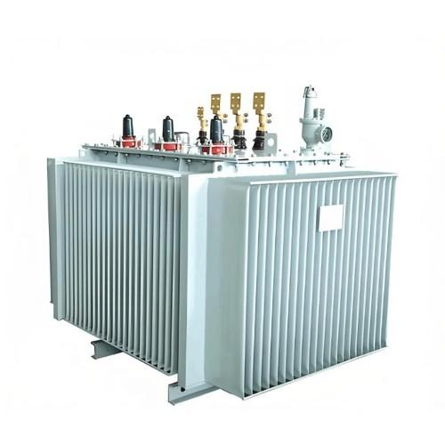
A surge arrester should be installed on the high-voltage side of the H61 distribution transformer. According to SDJ7–79 "Technical Code for Design of Overvoltage Protection of Electric Power Equipment," the high-voltage side of an H61 distribution transformer should generally be protected by a surge arrester. The grounding conductor of the arrester, the neutral point on the low-voltage side of the transformer, and the transformer’s metal casing should all be connected together and grounded at a common point. This method is also recommended in DL/T620–1997 "Overvoltage Protection and Insulation Coordination for AC Electrical Installations," issued by the former Ministry of Electric Power.
However, extensive research and operational experience have shown that even with surge arresters installed only on the high-voltage side, transformer damage still occurs under lightning impulse conditions. In general areas, the annual failure rate is about 1%; in high-lightning areas, it can reach around 5%; and in extremely severe lightning-prone regions with over 100 thunderstorm days per year, the annual failure rate can be as high as 50%. The primary cause is the so-called "forward and reverse transformation overvoltages" induced by lightning surges entering the high-voltage winding of the distribution transformer. The mechanisms of these overvoltages are as follows:
1. Reverse Transformation Overvoltage
When a lightning surge intrudes from the 3–10 kV high-voltage side and causes the arrester to operate, a large impulse current flows through the grounding resistance, creating a voltage drop. This voltage drop appears at the neutral point of the low-voltage winding, raising its potential. If the low-voltage line is relatively long, it behaves like a wave impedance to ground. Under the influence of this elevated neutral-point potential, a large impulse current flows through the low-voltage winding. The three-phase impulse currents are equal in magnitude and direction, generating a strong zero-sequence magnetic flux.
This flux induces a very high pulse voltage in the high-voltage winding according to the transformer turns ratio. These three-phase induced pulse voltages are equal in magnitude and direction. Since the high-voltage winding is typically connected in star configuration with an ungrounded neutral point, although high pulse voltages appear, no corresponding impulse current flows in the high-voltage winding to counterbalance the magnetizing effect. Thus, the entire impulse current in the low-voltage winding acts as magnetizing current, producing intense zero-sequence flux and inducing extremely high potentials on the high-voltage side.
Because the high-voltage terminal potential is clamped by the arrester’s residual voltage, this induced potential distributes along the winding, reaching its maximum at the neutral end. Consequently, the neutral-point insulation is prone to breakdown. Additionally, interlayer and interturn voltage gradients increase significantly, potentially causing insulation failure at other locations. This type of overvoltage originates from a high-voltage-side incoming surge and is electromagnetically coupled back to the high-voltage winding via the low-voltage winding—commonly known as "reverse transformation."
2.Forward Transformation Overvoltage
Forward transformation overvoltage occurs when a lightning surge enters through the low-voltage line. An impulse current then flows through the low-voltage winding, inducing a voltage in the high-voltage winding according to the turns ratio, which greatly raises the potential at the high-voltage neutral point. This also increases the interlayer and interturn voltage gradients. This process—where a low-voltage-side surge induces overvoltage on the high-voltage side—is called "forward transformation." Tests show that when a 10 kV surge enters the low-voltage side and the grounding resistance is 5 Ω, the interlayer voltage gradient in the high-voltage winding can exceed the full-wave impulse withstand strength of the interlayer insulation by more than 100%, inevitably causing insulation breakdown.
Therefore, ordinary valve-type or metal oxide surge arresters should also be installed on the low-voltage side of the H61 distribution transformer. In this protection scheme, the grounding conductors of both high- and low-voltage arresters, the low-voltage neutral point, and the transformer’s metal casing are all connected together and grounded at a single point (also referred to as "four-point bonding" or "three-in-one grounding").
Operational experience and experimental studies indicate that even for distribution transformers with good insulation, lightning-induced failures due to forward and reverse transformation overvoltages still occur when arresters are installed only on the high-voltage side. This is because high-voltage-side arresters cannot suppress forward or reverse transformation overvoltages. The interlayer voltage gradient under these overvoltages is proportional to the number of turns and depends on winding distribution; insulation breakdown can occur at the winding’s beginning, middle, or end—but the end is most vulnerable. Installing arresters on the low-voltage side can effectively limit both forward and reverse transformation overvoltages to a safe range.
Another protection method is separate grounding for high- and low-voltage sides. In this configuration, the high-voltage arrester is grounded independently, no arrester is installed on the low-voltage side, and the low-voltage neutral point and transformer casing are bonded together and grounded separately from the high-voltage grounding system.
This method leverages the earth’s attenuation effect on lightning waves to essentially eliminate reverse transformation overvoltage. Regarding forward transformation overvoltage, calculations show that reducing the low-voltage grounding resistance from 10 Ω to 2.5 Ω can lower the high-voltage forward transformation overvoltage by approximately 40%. With proper treatment of the low-voltage grounding electrode, forward transformation overvoltage can be eliminated entirely.
This protection scheme is simple and economical, though it imposes higher requirements on the low-voltage grounding resistance, giving it certain practical value for wider application.
In addition to the above methods, other lightning protection measures for distribution transformers include installing a balancing winding on the transformer core to suppress forward and reverse transformation overvoltages, or embedding metal oxide surge arresters directly inside the transformer.