Low-Voltage Distribution Lines and Power Distribution Requirements for Construction Sites

Low-voltage distribution lines refer to the circuits that, through a distribution transformer, step down the high voltage of 10 kV to the 380/220 V level—i.e., the low-voltage lines running from the substation to the end-use equipment.
Low-voltage distribution lines should be considered during the design phase of substation wiring configurations. In factories, for workshops with relatively high power demand, dedicated workshop substations are often installed, where transformers supply power directly to various electrical loads. For workshops with smaller loads, power is supplied directly from the main distribution transformer.
The layout design of low-voltage distribution lines is based on load category, magnitude, distribution, and load characteristics. Generally, there are two types of distribution methods: radial and trunk (or tree-type).
Radial circuits offer high reliability but involve higher investment costs. Therefore, trunk-type distribution is more commonly used in modern low-voltage systems due to its greater flexibility—when production processes change, major modifications to the distribution circuit are unnecessary. Thus, the trunk-type method features lower cost and higher adaptability. However, in terms of power supply reliability, it is inferior to the radial method.
1.Types of Low-Voltage Distribution Lines
There are two installation methods for low-voltage distribution lines: cable laying and overhead line erection.
Cable lines are buried underground, making them minimally affected by natural conditions such as wind or ice. Additionally, since no wires are visible above ground, they enhance urban aesthetics and building environments. However, cable installations involve higher investment costs and are more difficult to maintain and repair. Overhead lines have the opposite advantages and disadvantages. Therefore, unless special requirements exist, overhead lines are generally used for low-voltage distribution.
Low-voltage overhead lines typically use wooden or concrete poles, with insulators (porcelain bottles) fixing conductors onto crossarms mounted on the poles. The distance between two poles is approximately 30–40 meters within factory yards and can reach 40–50 meters in open areas. The spacing between conductors is usually 40–60 centimeters. Line routes should be as short and direct as possible while allowing for ease of installation and maintenance.
1.1 Construction Site Power Distribution
Electrical load conditions at construction sites differ from those in regular industrial plants. The magnitude and nature of loads vary with project progress—for example, initial construction stages mainly use transport and hauling machinery, while later stages may involve welding machines, etc. Therefore, the site’s total power demand should be determined based on the maximum calculated load of the peak construction phase.
Power supply at construction sites is temporary. All electrical equipment must allow for rapid installation and dismantling. On-site substations are preferably pole-mounted outdoor types. Trunk-type overhead lines are commonly used for wiring. When erecting lines, care must be taken not to obstruct traffic and to ensure ease of installation and removal. For underground projects or tunnel construction where space is limited, overhead line height cannot meet standard ground-level requirements.
In such cases, lighting circuits must use safety extra-low voltage (SELV) below 36 V, while 380/220 V power supply lines for motor loads should use flexible three-phase four-core cables with good insulation and moisture resistance. Cables should be laid according to construction progress and disconnected and removed when not in use to ensure safety.

1.2 Minimum Clearance Between Conductors and Ground
Distribution lines should not cross over roofs made of combustible materials, nor should they preferably cross buildings with fire-resistant roofs; if unavoidable, coordination with relevant authorities is required. The vertical clearance between conductors and buildings, at maximum sag, shall be no less than 3 meters for 1–10 kV lines, and no less than 2.5 meters for lines below 1 kV.
When distribution lines intersect with communication (low-voltage) lines, the power lines shall be installed above the communication lines. The vertical separation at maximum sag shall be no less than 2 meters for 1–10 kV lines, and no less than 1 meter for lines below 1 kV.
2.Distribution Boards at Construction Sites
Distribution boards at construction sites can be classified into main distribution boards, fixed sub-distribution boards, and mobile sub-distribution boards.
2.2 Main Distribution Board
If an independent transformer is used, both the transformer and the subsequent main distribution board are installed by the power supply authority. The main distribution board contains a main low-voltage circuit breaker, active and reactive energy meters, voltmeter, ammeter, voltage selector switch, and indicator lamps. All branch circuits at the construction site are connected to sub-distribution boards located downstream of this main board.
If a pole-mounted transformer is used, both the main and sub-distribution boards are mounted on the pole, with the bottom of the enclosure at least 1.3 meters above ground level. For larger transformers installed on ground platforms, enclosed switchgear cabinets may be used. Sub-distribution boards typically use DZ-series low-voltage circuit breakers.
The main circuit breaker is selected based on the transformer’s rated current, while branch circuits use smaller-capacity breakers sized according to the maximum rated current of each circuit. For circuits with small currents, residual current devices (RCDs) should be used (maximum RCD capacity: 200 A). The number of branch circuit breakers should exceed the designed number of branches by one or two to serve as spare circuits. Monitoring instruments such as ammeters and voltmeters are not installed in construction site distribution boards.
If an existing transformer (not dedicated to the site) is used, the main and sub-distribution functions are integrated into a single enclosure, with added active and reactive energy meters. From the main distribution board onward, the system adopts the TN-S three-phase five-wire configuration, and the metal enclosure of the distribution board must be connected to the protective earth (PE) conductor.
2.3 Fixed Sub-Distribution Board
At construction sites, cable laying is mostly done via direct burial, and the power supply system typically uses a radial configuration. Each fixed sub-distribution board serves as the endpoint of its branch circuit and is therefore usually placed near the electrical equipment it supplies.
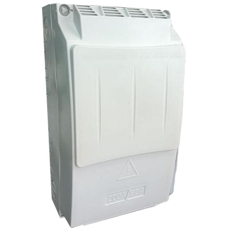
The enclosure of the fixed sub-distribution board is made of thin steel plate, with a rainproof top. The bottom of the box is installed at a height greater than 0.6 meters above ground, supported by angle steel legs. The box has doors on both sides. Inside, an insulating panel serves as the mounting base for electrical components. The box is equipped with a main 200–250 A switch—a four-pole RCD—sized according to the maximum rated current of all connected equipment.
Considering versatility, the design should accommodate common site equipment such as tower cranes or welding machines. Behind the main switch, several branch switches (also four-pole RCDs) are installed, with capacities combined according to typical appliance ratings—for example, a 200 A main RCD with four branches: two at 60 A and two at 40 A. Below each branch RCD, porcelain fuse holders are installed to provide a visible disconnection point and serve as equipment terminals. The upper terminals of the fuses connect to the lower terminals of the RCDs, while the lower terminals remain open for equipment connections. If needed, single-phase switches are also installed inside the box to supply single-phase appliances.
As the endpoint of a branch circuit, each fixed sub-distribution board must have repeated grounding to enhance the reliability of the protective earth connection.
After conductors enter the box, the neutral (working zero) conductor is connected to a terminal block. Phase conductors are directly connected to the upper terminals of the RCD. The protective earth (PE) conductor is clamped onto the grounding bolt on the enclosure and connected to a repeated grounding electrode. All downstream PE conductors from this distribution board are connected to this same bolt.
2.4 Mobile Sub-Distribution Board
The mobile sub-distribution board has the same internal configuration as the fixed type. It is connected via flexible rubber-sheathed cable to a fixed sub-distribution board and moved as close as possible to the equipment it serves—for example, from a lower floor up to a construction level above. The box also uses RCDs, but with smaller capacities than fixed boxes. Single-phase switches and sockets are added to provide single-phase power for single-phase appliances. The metal enclosure must be connected to the protective earth conductor.