• Product
  • Suppliers
  • Manufacturers
  • Solutions
  • Free tools
  • Knowledges
  • Experts
  • Communities
Search


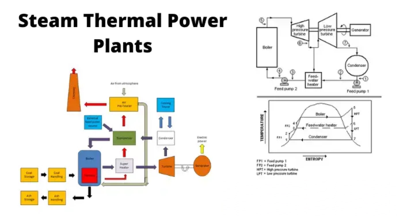
Flow Diagram of a Steam Thermal Power Plant

Master Electrician
Field: Basic Electrical
0
China

WechatIMG1762.jpeg

A thermal power generating plant works based on the Rankine Cycle. There are mainly three primary inputs given to thermal power generating plants for producing electricity. These three most essential elements are coal, air, and water.

Coal is used as fuel here because we are going to draw the flow diagram of a coal thermal power generating plant. Coal creates required heat energy by combustion in the furnace.

Air is supplied to the furnace to accelerate the combustion rate of the coal and to continue the flow of flue gases inside the heating system. Water is required in a thermal power plant inside a boiler to produce steam. This steam drives the turbine.

The turbine is coupled to the shaft of a generator which generates electrical power as the output of the system. Depending on these three primary inputs there are three basic flow circuits that work on a thermal power generating plant.

Coal Circuit

The coal is transported from coal supplying authorities to the coal storage yard of the generating plant. From here the coal is delivered to the pulverized coal plants with the help of a conveyor.

After removing unwanted substances from the coal, it is pulverized in coal dust. Pulverisation makes the coal more efficient for burning. After the combustion of the coal, the ash is collected to the ash handling plant. Then the ash is finally collected to the ash storage yard.
diagram of thermal power plant

Air Circuit

Air is supplied to the furnace with forced draught fans. But it is not directly charged to the boiler furnace before it is charged to the boiler furnace it is passed through an air preheater.

In the air preheater, the heat of the exhaust flue gases is transferred to the inlet air before it enters the furnace.

In the furnace, this air supplies required oxygen for combustion. Then this air carries the generated heat and flue gases due to the combustion through the boiler tube surfaces.

Here significant part of the heat is transferred to the boiler. The flue gases then pass through the superheater where the steam coming from the boiler gets further heated up to the spearheading temperatures.

Then the flue gases come to the economizer where some of the remaining portions of the heat of flue gases are utilized for increasing the temperature of the water before it enters the boiler.

The flue gases then pass through the air preheater where a portion remaining heat is transferred to the inlet air before it enters the boiler furnace.

After passing through the air preheater, the gases ultimately go to the chimney by induced draught fans.

Normally in thermal power plants, forced draught is used at the entry of air from the atmosphere, and induced draught is used at the exit of flue gases from the system through the chimney.

Water Steam Circuit

The water-steam circuit of a thermal power generating plant is a semi-closed circuit. Here comparatively not much water is required to supply to the boiler from external sources since the same water is reused again and again by condensing the steam after its mechanical work of rotating turbine.

Here, water is first taken from a river or any other suitable natural source of water.

This water then is taken to the water treatment plant for removing unwanted particles and substances from the water. This water is then fed to the boiler through an economizer.

In the boiler, the water is converted into steam. This steam then goes to the super-heater, where the steam is heated up to the superheating temperature. The superheated steam then goes to the turbine through a series of nozzles.

At the outlet of these nozzles, the high pressure and high-temperature steam suddenly expands and hence gets kinetic energy. Because of this kinetic energy, the steam rotates the turbine.

The turbine is coupled with a generator and the generator produces alternating electricity to the grid.

Suddenly expanded steam exhaust from the turbine to the condenser. Where the steam is condensed back to the water with the help of a water circulating cooling system associated with cooling towers.

This condensed water is then fed back to the boiler through the economizer. The water supply from an external source of water is limited here because of using condensed steam in the boiler system of the thermal power generating plant.

Statement: Respect the original, good articles worth sharing, if there is infringement please contact delete.

Give a tip and encourage the author!
Recommended
Why Regular Transformer Maintenance Matters: 5 Serious Consequences of Neglecting It
I. Allowable TemperatureWhen a transformer is in operation, its windings and iron core generate copper loss and iron loss. These losses are converted into heat energy, causing the temperature of the transformer's iron core and windings to rise. If the temperature exceeds the allowable value for a long time, the insulation will gradually lose its mechanical elasticity and age.The temperature of each part of the transformer during operation is different: the winding temperature is the highest, fol
Rockwell
09/12/2025
How to Implement Condition-Based Maintenance for Power Transformers? A Complete 4-Step Process Analysis
1. Definition of Condition-Based MaintenanceCondition-based maintenance refers to a maintenance method where decisions on whether and how to perform maintenance are determined based on the real-time operating status and health condition of equipment. It has no fixed maintenance methods or schedules. The prerequisite for condition-based maintenance is the establishment of equipment parameters and the comprehensive analysis of various operational information of the equipment, so as to make reasona
Noah
09/12/2025
Can't choose a dry-type transformer? Get expert advice – free.
Traction Rectifier TransformersRated capacity: 800 to 4400 kVA; Voltage class: 10 kV and 35 kV; Rectifier pulse number: 12-pulse and 24-pulse. Compared with 12-pulse rectifier circuits, 24-pulse rectifier circuits can reduce the harmonic pollution of the power grid by 50%, and no filtering equipment is needed at this location. It is suitable for power supply systems of urban subways and rail transit.Excitation Rectifier TransformersRated capacity: 315 to 3000 × 3 kVA; Voltage class: 10 kV, 13.8
Vziman
09/12/2025
High harmonics? Your transformer may be overheating and aging fast.
This report is based on the analysis of one-day power quality monitoring data of your company's distribution system. The data shows that there is significant three-phase current harmonic distortion in the system (with a high total harmonic distortion of current, THDi). In accordance with international standards (IEC/IEEE), harmonic currents at this level have posed substantial risks to the safe, reliable, and economical operation of the power supply transformer, mainly manifested in additional h
Leon
09/12/2025
Seed Inquiry
Download
Get the IEE Business Application
Use the IEE-Business app to find equipment, obtain solutions, connect with experts, and participate in industry collaboration anytime, anywhere—fully supporting the development of your power projects and business.