Hydro Power Plant | Construction Working and History of Hydro power plant

electricity-today
03/19/2024

WechatIMG1769.jpeg

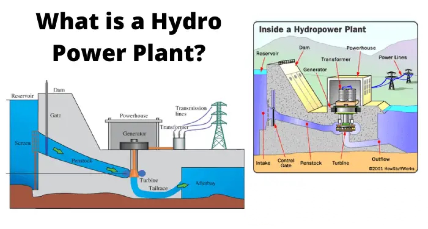
In hydroelectric power station the kinetic energy developed due to gravity in a falling water from higher to lower head is utilised to rotate a turbine to produce electricity. The potential energy stored in the water at upper water level will release as kinetic energy when it falls to the lower water level. This turbine rotates when the following water strikes the turbine blades. To achieve a head difference of water hydroelectric electric power station are generally constructed in hilly areas. In the way of the river in hilly areas, an artificial dam is constructed to create required water head. From this dam water is allowed to fall toward downstream in a controlled way to turbine blades. As a result, the turbine rotates due to the water force applied to its blades and hence the alternator rotates since the turbine shaft is coupled with alternator shaft.
The main advantage of an
electric power plant is that it does not require any fuel. It only requires water head which is naturally available after the construction of the required dam.

No fuel means no fuel cost, no combustion, no generation of flue gases, and no pollution in the atmosphere. Due to the absence of fuel combustion, the hydroelectric power plant itself is very neat and clean. In addition to that, it does not produce any pollution to the atmosphere. Also from constructional point of view, it is simpler than any thermal and nuclear power plant.
The constructional cost of a hydroelectric power plant maybe higher than that of other conventional
thermal power plants because of construction of a huge dam across the flowing river. The engineering cost in addition to the constructional cost is also high in a hydroelectric power plant. Another disadvantage of this plant is that it cannot be constructed anywhere according to the load centres.
So,
long transmission lines are required to transmit the generated power to the load centres.
Thus the transmission cost may be high enough.

In spite of that, the stored water in the dam can also be utilised for irrigation and any other similar purposes. Sometimes by creating such dam in the way of the river, occasional floods in the downstream of the river can be controlled significantly.

hydro power plant
There are only six primary components required to construct a hydroelectric power plant. These are dam, pressure tunnel, surge tank, valve house, penstock, and powerhouse.

The dam is an artificial concrete barrier constructed across the way of the river. The catchment area behind the dam creates a huge water reservoir.
The pressure tunnel takes water from the dam to the valve house.
In the valve house, there are two types of valves available. The first one is main sluicing valve and the second one is an automatic isolating valve. The sluicing valves control the water flowing to the downstream and automatic isolating valves stop the water flow when the electrical load is suddenly thrown off from the plant. Automatic isolating valve is a protecting valve does not play any direct role control the flow of water to the turbine. It only operates during emergency to protect the system from burst out.

The penstock is a steel pipeline of suitable diameter connected between the valve house and powerhouse. The water flows down from upper valve house to lower powerhouse through this penstock only.
In the powerhouse there are water turbines and
alternators with associated step up transformers and switchgear systems to generate and then facilitate transmission of electricity.
At last, we will come to the surge tank. The surge tank is also a protective accessory associated with hydroelectric power plant. It is situated just before the valve house. The height of the tank must be greater than the head of the water stored in the water reservoir behind the dam. This is an open top water tank.

The purpose of this tank is to protect the penstock from bursting out when suddenly turbine refuses to take water. At the entry point of turbines, there are turbine gates control by governors. The governor opens or closes the turbine gates according to the fluctuation of the electrical load. If the electrical load is suddenly thrown off from the plant, the governor closes the turbine gates and water is blocked in the penstock. Sudden stopping of water can cause a serious burst of penstock pipeline. The surge tank absorbs this back pressure by swing the level water in this tank.

Statement: Respect the original, good articles worth sharing, if there is infringement please contact delete.

electricity-today

Electrical Operations provides detailed insights into safe and efficient electrical procedures, guiding practitioners through every step of handling electrical systems.

What is Steady State Stability in Power System?
Definition of Steady State StabilitySteady state stability is defined as the capability of an electric power system to sustain its initial operating condition following a small disturbance, or to converge to a state closely approximating the initial condition when the disturbance persists. This concept holds critical significance in power system planning and design, the development of specialized automatic control devices, the commissioning of new system components, and the adjustment of operati
Edwiin
07/26/2025
What is Voltage Stability in Power Systems?
Definition of Voltage StabilityVoltage stability in a power system is defined as the ability to maintain acceptable voltages at all buses under both normal operating conditions and after being subjected to a disturbance. In normal operation, the system’s voltages remain stable; however, when a fault or disturbance occurs, voltage instability may arise, leading to a progressive and uncontrollable voltage decline. Voltage stability is sometimes referred to as "load stability."Voltage instability c
Encyclopedia
07/26/2025
Difference Between Shunt and Series Voltage Regulator
Linear voltage regulators are mainly classified into two types: shunt voltage regulators and series voltage regulators. The key difference between them lies in the connection of the control element: in a shunt voltage regulator, the control element is connected in parallel with the load; in contrast, in a series voltage regulator, the control element is connected in series with the load. These two types of voltage regulator circuits operate on different principles and thus have their own advanta
Edwiin
07/25/2025
What is Dual Trace Oscilloscope?
What is Dual Trace Oscilloscope?DefinitionA dual-trace oscilloscope uses a single electron beam to generate two separate traces, each deflected by an independent input source. To produce these two traces, it primarily employs two operating modes—alternate mode and chopped mode—controlled by a switch.Purpose of a Dual-Trace OscilloscopeWhen analyzing or studying multiple electronic circuits, comparing their voltage characteristics is often critical. While one could use multiple oscilloscopes for
Encyclopedia
07/25/2025
Inquiry
Download
IEE-Business is dedicated to serving the personnel in the global power industry.
Join IEE-Business, not only can you discover power equipment and power knowledge, but also canhnd like - minded friends!