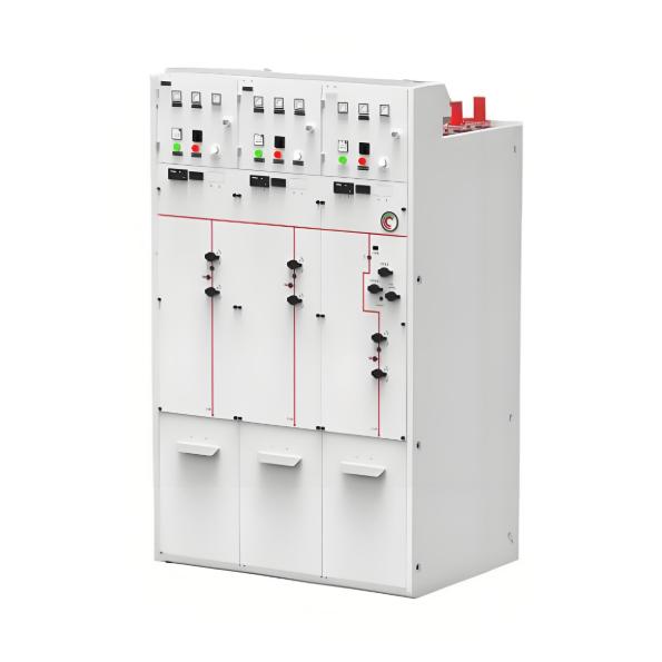
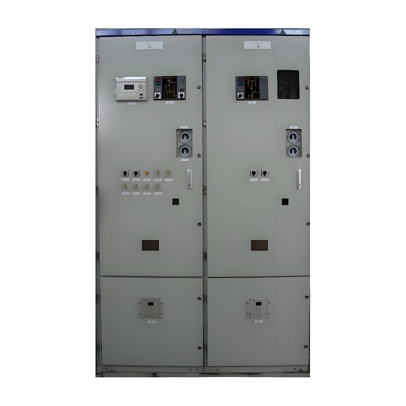
Ring main units (RMUs) are used in secondary power distribution, directly connecting to end-users such as residential communities, construction sites, commercial buildings, highways, etc.
In a residential substation, the RMU introduces 12 kV medium voltage, which is then stepped down to 380 V low voltage through transformers. The low-voltage switchgear distributes electrical energy to various user units. For a 1250 kVA distribution transformer in a residential community, the medium-voltage ring main unit typically adopts a configuration of two incoming feeders and one outgoing feeder, or two incoming feeders with multiple outgoing feeders, with each outgoing circuit connected to a transformer. For a 1250 kVA transformer, the current on the 12 kV ring main unit side is 60 A. A fused switchgear combination unit (FR unit), consisting of a load break switch and a fuse, is used. A 100 A fuse is employed, where the load break switch controls energizing or de-energizing the transformer, and the fuse provides short-circuit protection for the transformer. The 1250 kVA transformer outputs 380 V low-voltage current of 2500 A, which is distributed via standardized low-voltage switchgear from State Grid.
SF6 gas-insulated RMUs are compact in size, and the common-tank design is even smaller and cost-effective. Benefiting from the excellent insulation and arc-quenching properties of SF6 gas, the load break switches inside the switchgear use SF6 gas for arc extinction, capable of interrupting both isolation and active load currents up to 630 A.
For environmentally friendly gas-insulated RMUs, due to the lack of an alternative eco-friendly gas that matches SF6 in both insulation and arc-quenching performance, and since disconnectors cannot interrupt load current, a combination of a disconnector and a vacuum load break switch is commonly used to fulfill the function that previously required only one switch.
The top row in the figure below shows the primary circuit scheme of a conventional SF6 RMU, while the bottom row shows the primary circuit scheme of an environmentally friendly gas-insulated RMU.

It can be seen that for the F-type cabinet with ring-in and ring-out load break switches, isolation plus a vacuum switch is required; for the transformer outgoing FR cabinet, isolation plus a vacuum switch plus a fuse is also needed, making the switching configuration more complex.
The electrical parameters of the ring main unit load break switch are as follows:
• Rated current: 630 A
• Rated short-time withstand current: 20/4 (25/4*) kA/4 s
• Rated short-circuit closing current: 50 (63*) kA
• Mechanical endurance of load break switch: Class M1, 5000 operations
• Mechanical endurance of earthing switch: Class M1, 3000 operations
• Electrical endurance of load break switch: Class E3, 200 operations
Therefore, Schneider has introduced a parallel vacuum arc-extinguishing method, i.e., installing a vacuum interrupter in parallel within the switch. During the opening process, the moving contact linkage of the vacuum interrupter is synchronously driven, transferring the arc into the vacuum interrupter where it is extinguished.
After arc extinction, the contacts of the vacuum interrupter return to the closed position, and during the subsequent closing operation of the switch, the vacuum interrupter does not actuate.
This design requires only one operating mechanism, compared to the two separate structures of a disconnector and a vacuum switch, resulting in a smaller size and lower cost. However, compared to two independent switches, the parallel switching mechanism imposes higher requirements on design, manufacturing process, and reliability to ensure accurate switch operation.
This type of parallel vacuum interrupter load break switch comes in different structural forms, but the underlying principle is the same.
A miniaturized vacuum interrupter is integrated with the main switch contacts, serving only to interrupt small currents up to 630 A.
In line with the "Dual Carbon" goals, environmentally friendly gas-insulated switchgear represents an inevitable trend. Without technological advancement, simply piling components leads to increased material and resource consumption, higher losses, and hinders sustainable development. While researching new alternative gases and arc-quenching methods, pursuing solutions that simplify mechanisms, enable easier operation, and improve reliability is a viable path forward for advanced equipment manufacturers and products. Customers should also choose technologically advanced alternative products to help achieve the Dual Carbon goals sooner.