
Surge Arresters: Principles and Applications
A surge arrester is a critical device used to protect structures and electrical equipment from lightning strikes. It rapidly diverts and dissipates lightning current, thereby safeguarding equipment and personnel. The following provides a detailed explanation of its working principles.
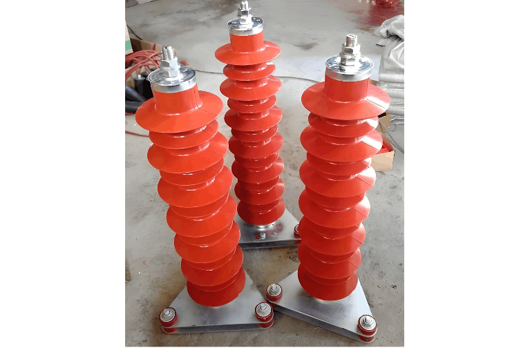
1. Basic Construction of Surge Arresters
A surge arrester typically consists of two main components: a gas discharge tube and a metal oxide varistor (MOV).
Gas Discharge Tube: This is the core component of the arrester, comprising two electrodes enclosed in a tube filled with a specific gas. When a high voltage from lightning occurs, the gas discharge tube ionizes and breaks down, creating a low-resistance path that channels the lightning current safely to ground.
Metal Oxide Varistor (MOV): Serving as a supplementary component, the MOV provides additional overvoltage protection. Under normal conditions, it exhibits high resistance. When the gas discharge tube activates, the MOV rapidly responds to limit residual current and clamp transient overvoltages.
2. Working Principle of Surge Arresters
The operation of a surge arrester can be divided into two stages: the equilibrium stage and the breakdown stage.
Equilibrium Stage:
Under normal operating conditions, in the absence of lightning, both the gas discharge tube and the MOV exhibit very high resistance and are effectively non-conductive. The arrester has no influence on the circuit.
Breakdown Stage:
When lightning strikes a structure or equipment, a high-voltage surge is generated. Once the voltage exceeds the breakdown threshold of the gas discharge tube, it ionizes rapidly, forming a low-impedance path. The lightning current is then safely diverted through the tube to ground, protecting the equipment and personnel.
Simultaneously, the MOV plays a crucial role. It quickly transitions to a low-resistance state in response to the overvoltage, further limiting the surge current and preventing excessive stress on the protected equipment.
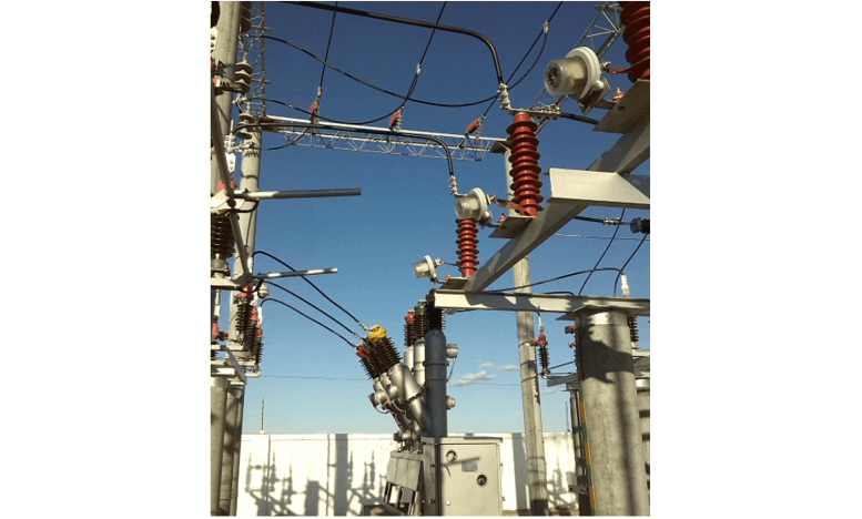
3. Applications of Surge Arresters
Surge arresters are widely used in various structures and electrical systems, including residential buildings, commercial facilities, industrial plants, and power networks. Their primary function is to protect against lightning-induced damage, preventing fires, explosions, and equipment failure.
Arresters are categorized into different types—low-voltage, medium-voltage, and high-voltage—based on their application and rated voltage, allowing for appropriate selection according to system requirements.
4. Maintenance and Testing
To ensure reliable performance, surge arresters require regular maintenance and inspection.
Maintenance: Periodic visual inspections should be conducted to check for physical damage, corrosion, or contamination. Damaged units must be replaced promptly. The surrounding area should be kept clean and free of obstructions that could impair operation.
Testing: The condition of a surge arrester can be assessed by measuring its insulation resistance. Under normal conditions, the resistance is very high (nearly infinite). A significantly reduced resistance indicates potential failure and necessitates replacement.
Additionally, specialized monitoring systems can be used to continuously track the arrester’s status, enabling early detection of issues and timely corrective actions.
Summary
Surge arresters are essential protective devices for structures and electrical equipment against lightning. By combining a gas discharge tube and a metal oxide varistor, they effectively divert and dissipate lightning currents. Their operation involves an equilibrium stage under normal conditions and a breakdown stage during surges, where a low-impedance path is established to safely route current to ground. Widely applied across various installations, surge arresters require regular maintenance and testing to ensure continued reliability and protection.


