Reactance Relay
A reactance relay is a high-speed relay composed of two elements: an overcurrent element and a current-voltage directional element. The current element generates positive torque, while the current-voltage directional element produces torque opposite to the current element, depending on the phase angle between the current and voltage.
The reactance relay is an overcurrent relay with directional limitation. The directional element is designed to generate maximum negative torque when its current lags behind its voltage by 90°. Induction cup or double induction loop structures are ideally suited for actuating reactance-type distance relays.
Construction of Reactance Relay
A typical reactance relay using an induction cup structure is shown in the figure below. It features a four-pole configuration with operating coils, polarizing coils, and restraining coils. The operating torque is generated by the interaction of magnetic fluxes from current-carrying coils (i.e., the interaction of fluxes from poles 2, 3, and 4), while the restraining torque is produced by the interaction of fluxes from poles 1, 2, and 4.
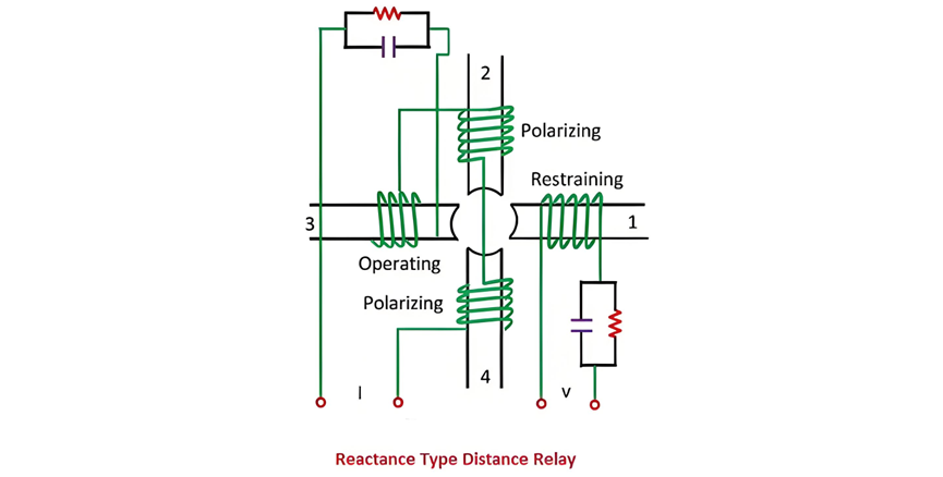
In the operational mechanism of a reactance relay, the operating torque is directly proportional to the square of the current, indicating that fluctuations in current significantly impact the torque magnitude. Conversely, the restraining torque is proportional to the product of voltage and current, multiplied by cos(Θ−90°), meaning it is influenced by voltage, current, and their phase angle.
As illustrated in the figure, a resistor-capacitor (RC) circuit is employed to precisely adjust and achieve the desired maximum torque angle by leveraging impedance characteristics to control phase shifts. When denoting the control effect as -k3, the torque equation can be explicitly expressed as a dynamic equilibrium relationship between the operating and restraining torques. This equation clearly demonstrates the relay's torque variations under different electrical parameters, providing critical theoretical support for performance analysis and design optimization.

where Θ, is defined as positive when I lag behind V. At the balance point net torque is zero, and hence

In the above equation, the spring control effect is neglected due to its minimal impact, i.e., K3 = 0.
Operating Characteristic of Reactance Relay
As shown in the figure, the operating characteristic of a reactance relay appears as a vertical line perpendicular to the horizontal axis. Here, X represents the reactance value of the protected line, and R is the resistance component. This characteristic indicates that the relay's operation depends solely on the reactance component, unaffected by resistance changes. The area below the operating characteristic curve is the positive torque region (i.e., the relay's operating zone). When the measured impedance falls into this region, the relay acts immediately, making this characteristic particularly suitable for short-line protection as it effectively avoids interference from transition resistance and ensures fast, reliable operation.
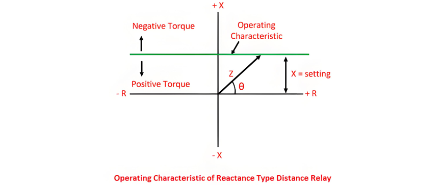
If τ in the torque equation is not 90º, a straight-line characteristic non-parallel to the R-axis is obtained, and such a relay is called an angle impedance relay.

This relay cannot distinguish faults in its own or adjoining sections on transmission lines. Its directional unit differs from impedance relays' as restraining reactive volt-amperes are near zero here. Thus, it requires a directional unit inactive under load. Ideal for ground fault protection, its reach stays unaffected by fault impedance.