• Product
  • Suppliers
  • Manufacturers
  • Solutions
  • Free tools
  • Knowledges
  • Experts
  • Communities
Search


Transducer vs Inverse Transducer | -Convert Physical to Electrical

Edwiin
Field: Power switch
China

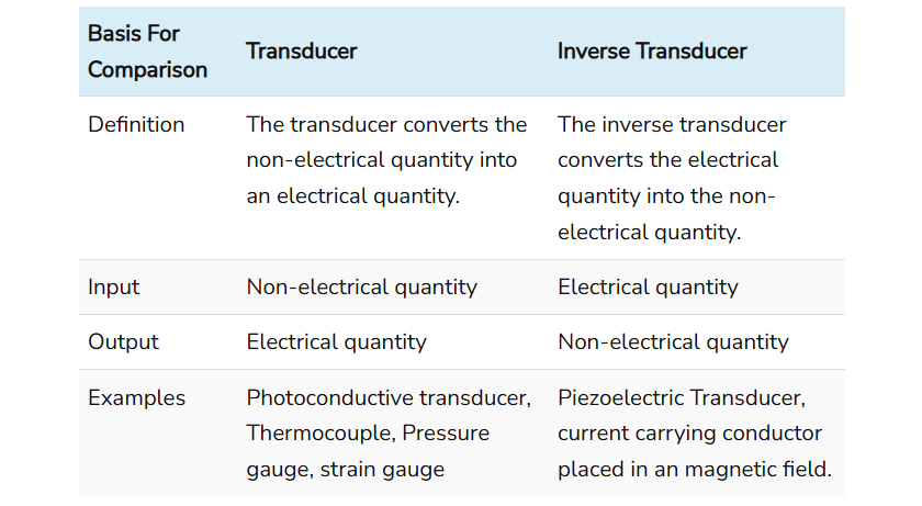
One of the primary differences between a transducer and an inverse transducer is that a transducer converts a non-electrical quantity into an electrical quantity, whereas an inverse transducer converts an electrical quantity into a non-electrical quantity. Other differences between the two are summarized in the comparison chart below.

The control of physical quantities such as flow, rate, position, speed, temperature, and pressure depends on the accurate measurement of these quantities. In simple terms, effective control is only possible when these physical parameters are precisely measured.

To measure physical quantities, it is essential to convert them into electrical signals, which is accomplished using a transducer. For example, in a servomechanism, the position of a shaft is controlled by accurately measuring its position.

Comparison Chart

Definition of Transducer

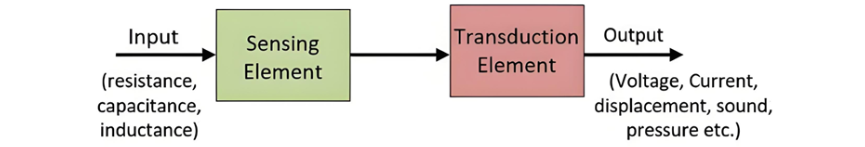
A transducer is a device that converts physical quantities—such as pressure, brightness, and displacement—into electrical signals. This conversion process is known as transduction.

Examples: A thermocouple converts temperature into a small voltage, and an LVDT (Linear Variable Differential Transformer) is used to measure displacement.

Definition of Inverse Transducer

An inverse transducer converts an electrical quantity into a non-electrical quantity. In other words, it functions as an actuator with an electrical input and a non-electrical output.

Examples: Analog ammeters and voltmeters convert current or voltage into mechanical displacement. An oscilloscope converts electrical signals into visible physical deflection on a screen.

Key Differences Between Transducer and Inverse Transducer

  • A transducer converts a non-electrical quantity into an electrical quantity, while an inverse transducer converts an electrical quantity into a non-electrical quantity.

  • The input to a transducer is a non-electrical quantity, whereas the input to an inverse transducer is an electrical quantity.

  • The output of a transducer is an electrical quantity, while the output of an inverse transducer is a non-electrical quantity.

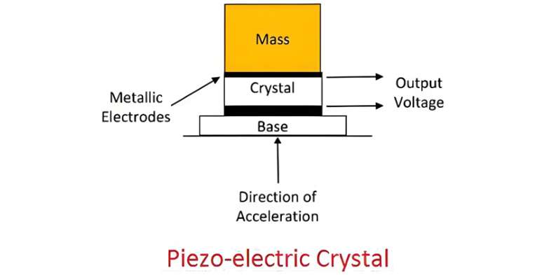
  • Examples of transducers include photoconductive cells, thermocouples, and pressure sensors. Examples of inverse transducers include piezoelectric actuators and current-carrying conductors placed in a magnetic field.

Conclusion

A transducer converts a physical quantity into an electrical quantity, whereas an inverse transducer converts an electrical quantity into a physical quantity.

Give a tip and encourage the author!
Recommended
Why Regular Transformer Maintenance Matters: 5 Serious Consequences of Neglecting It
I. Allowable TemperatureWhen a transformer is in operation, its windings and iron core generate copper loss and iron loss. These losses are converted into heat energy, causing the temperature of the transformer's iron core and windings to rise. If the temperature exceeds the allowable value for a long time, the insulation will gradually lose its mechanical elasticity and age.The temperature of each part of the transformer during operation is different: the winding temperature is the highest, fol
Rockwell
09/12/2025
How to Implement Condition-Based Maintenance for Power Transformers? A Complete 4-Step Process Analysis
1. Definition of Condition-Based MaintenanceCondition-based maintenance refers to a maintenance method where decisions on whether and how to perform maintenance are determined based on the real-time operating status and health condition of equipment. It has no fixed maintenance methods or schedules. The prerequisite for condition-based maintenance is the establishment of equipment parameters and the comprehensive analysis of various operational information of the equipment, so as to make reasona
Noah
09/12/2025
Can't choose a dry-type transformer? Get expert advice – free.
Traction Rectifier TransformersRated capacity: 800 to 4400 kVA; Voltage class: 10 kV and 35 kV; Rectifier pulse number: 12-pulse and 24-pulse. Compared with 12-pulse rectifier circuits, 24-pulse rectifier circuits can reduce the harmonic pollution of the power grid by 50%, and no filtering equipment is needed at this location. It is suitable for power supply systems of urban subways and rail transit.Excitation Rectifier TransformersRated capacity: 315 to 3000 × 3 kVA; Voltage class: 10 kV, 13.8
Vziman
09/12/2025
High harmonics? Your transformer may be overheating and aging fast.
This report is based on the analysis of one-day power quality monitoring data of your company's distribution system. The data shows that there is significant three-phase current harmonic distortion in the system (with a high total harmonic distortion of current, THDi). In accordance with international standards (IEC/IEEE), harmonic currents at this level have posed substantial risks to the safe, reliable, and economical operation of the power supply transformer, mainly manifested in additional h
Leon
09/12/2025
Seed Inquiry
Download
Get the IEE Business Application
Use the IEE-Business app to find equipment, obtain solutions, connect with experts, and participate in industry collaboration anytime, anywhere—fully supporting the development of your power projects and business.