Guide to Characteristics, Installation, Operation, and Commissioning of SC Series Dry-Type Transformers

Dry-type transformers refer to power transformers in which the core and windings are not immersed in oil. Instead, the coils and core are cast together (typically with epoxy resin) and cooled by either natural air convection or forced-air cooling. As a relatively newer type of power distribution equipment, dry-type transformers have been widely used in power transmission and distribution systems in factory workshops, high-rise buildings, commercial centers, airports, ports, subways, and offshore oil platforms. They can also be combined with switchgear cabinets to form compact, integrated prefabricated substations.
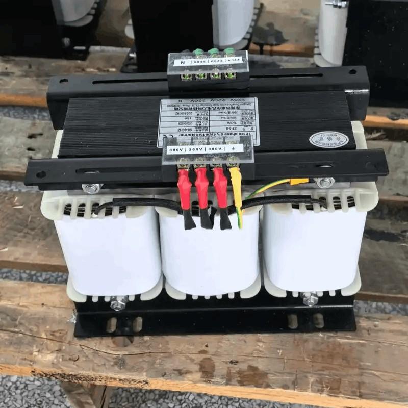
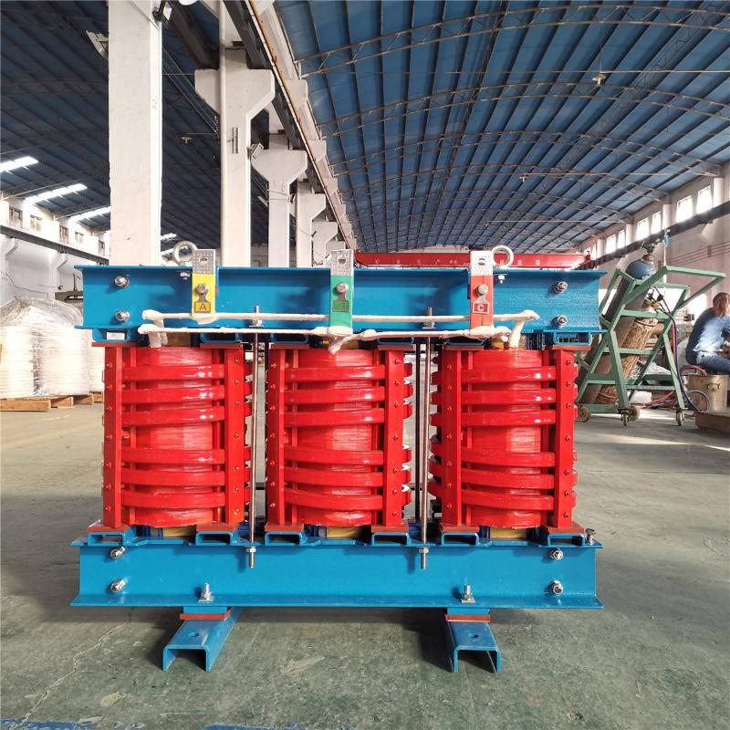
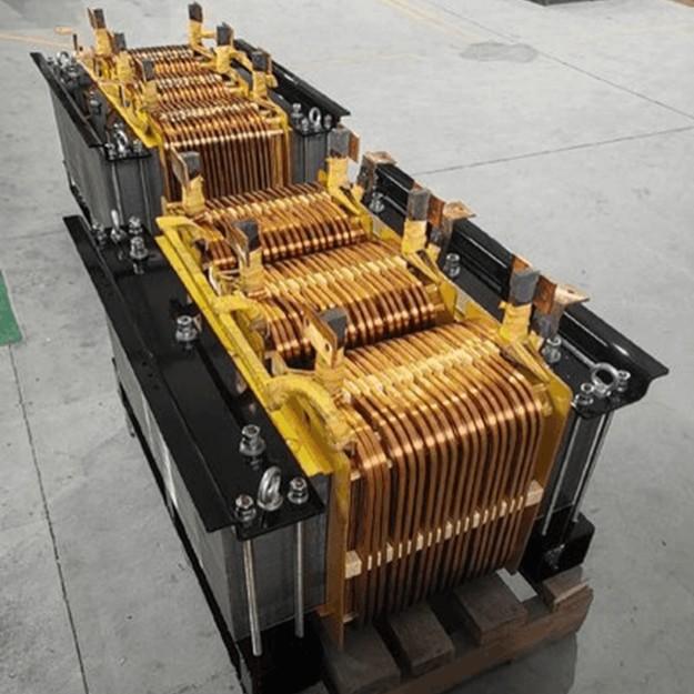
Currently, most dry-type power transformers produced in China are three-phase, solid-molded SC-series units, such as: SCB9 series three-phase wound-coil transformers, SCB10 series three-phase foil-wound transformers, and SCB9 series three-phase foil-wound transformers. Their voltage ratings generally range from 6 kV to 35 kV, with maximum capacities reaching up to 25 MVA. This document will focus on the SC-series three-phase wound-coil dry-type transformers to provide a detailed explanation of their characteristics and installation/commissioning procedures.
1. Characteristics of Dry-Type Transformers
Compared with oil-immersed transformers, dry-type transformers contain no oil, thus eliminating risks of fire, explosion, and pollution. Therefore, electrical codes and regulations do not require dry-type transformers to be installed in a separate room. Especially in newer series, losses and noise levels have been reduced to new lows, making it feasible to install the transformer in the same distribution room as low-voltage switchboards.
1.1 Temperature Control System of Dry-Type Transformers
The safe operation and service life of a dry-type transformer largely depend on the safety and reliability of the winding insulation. Insulation failure caused by winding temperatures exceeding the insulation’s thermal withstand limit is one of the main reasons for abnormal transformer operation. Therefore, monitoring the operating temperature of the transformer and implementing alarm and control functions are extremely important.
1.2 Protection Methods of Dry-Type Transformers
Depending on the environmental conditions and protection requirements, dry-type transformers can be equipped with different enclosures. IP23-rated enclosures are commonly selected, which prevent solid foreign objects larger than 12 mm and small animals such as rats, snakes, cats, and birds from entering and causing severe faults like short circuits and power outages, thereby providing a safety barrier for live parts. If the transformer must be installed outdoors, an IP23 enclosure can be used; in addition to the protection offered by IP20, it also prevents water droplets falling at angles up to 60° from the vertical direction. However, an IP23 enclosure reduces the transformer’s cooling capacity, so attention must be paid to derating its operating capacity accordingly.

1.3 Cooling Methods of Dry-Type Transformers
Dry-type transformers use two cooling methods: natural air cooling (AN) and forced air cooling (AF). Under natural air cooling, the transformer can operate continuously at its rated capacity. Under forced-air cooling, the transformer’s output capacity can be increased by 50%. This mode is suitable for intermittent overload operation or emergency overload conditions. However, during overload operation, load losses and impedance voltage increase significantly, resulting in uneconomical operation; therefore, prolonged continuous overload operation should be avoided.
1.4 Overload Capability of Dry-Type Transformers
The overload capability of a dry-type transformer depends on ambient temperature, the load condition prior to overloading (initial load), the insulation’s heat dissipation performance, and the thermal time constant. If needed, the manufacturer can provide an overload curve for the dry-type transformer. Currently, China’s annual production capacity of resin-insulated dry-type transformers has reached 10,000 MVA, making it one of the world’s largest producers and consumers of dry-type transformers.
With the widespread adoption of low-noise (for distribution transformers ≤2500 kVA, noise is controlled below 50 dB) and energy-saving SC(B)9 series transformers (which reduce no-load losses by up to 25%), the performance specifications and manufacturing technology of dry-type transformers in China have reached world-advanced levels.
2.Installation and Commissioning of Dry-Type Transformers
2.1 Inspection Before Installation (Upon Unpacking)
Check whether the packaging is intact. After unpacking the transformer, verify that the nameplate data matches the design requirements, that all factory documentation is complete, that the transformer itself is undamaged with no signs of external damage, that components have not shifted or been damaged, that electrical support parts or connecting wires are undamaged, and finally confirm that spare parts are neither damaged nor missing.
2.2 Transformer Installation
First, inspect the transformer foundation and check whether the embedded steel plates are level. There should be no voids beneath the steel plates to ensure good seismic resistance and sound absorption performance of the foundation; otherwise, the noise level of the installed transformer will increase. Then, use rollers to move the transformer to its installation position, remove the rollers, and precisely adjust the transformer to its designed location, ensuring the leveling error meets design requirements. Finally, weld four short channel steel sections near the four corners of the transformer base onto the embedded steel plates to prevent displacement during operation.
2.3 Transformer Wiring
During wiring, maintain the minimum required clearance between live parts and between live parts and ground, especially the distance between cables and the high-voltage winding. High-current low-voltage busbars must be independently supported and should not be directly connected to the transformer terminals, as this would create excessive mechanical tension and torque. When the current exceeds 1000 A (e.g., the 2000 A low-voltage busbar used in this project), a flexible connection must be installed between the busbar and the transformer terminal to compensate for thermal expansion and contraction of the conductor and to isolate vibration between the busbar and the transformer. All electrical connections must maintain adequate contact pressure and should use elastic elements (such as disc springs or spring washers). When tightening connection bolts, a torque wrench must be used, following the manufacturer’s recommended torque values as shown in Table 1:
| Screw Size | M8 | M10 | M12 | M16 |
| Torque (N·m) | 10 |
25 | 30 | 40 |
| Torque (kg·m) | 1 |
2.5 | 3 |
4 |
2.4 Transformer Grounding
The grounding point of the transformer is located on the base of the low-voltage side, with a dedicated grounding bolt provided and marked with a grounding symbol. The transformer must be reliably connected to the protective grounding system through this point. When the transformer is equipped with an enclosure, the enclosure shall be reliably connected to the grounding system. In case of a three-phase four-wire system on the low-voltage side, the neutral conductor must also be reliably connected to the grounding system.
2.5 Pre-Operation Inspection
Check that all fasteners are secure and not loose, that all electrical connections are correct and reliable, and that the insulation clearances between live parts and between live parts and ground comply with specifications. There should be no foreign objects near the transformer, and the coil surfaces should be clean.
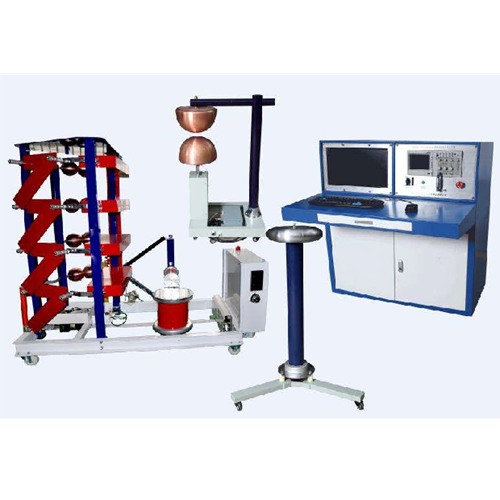
2.6 Pre-Commissioning Tests
Verify the transformer’s voltage ratio and connection group designation. Measure the DC resistance of both high- and low-voltage windings and compare the results with the manufacturer’s factory test data.
Check the insulation resistance between windings and between windings and ground. If the measured insulation resistance is significantly lower than the factory values, it indicates that the transformer has absorbed moisture. If the insulation resistance drops below 1000 Ω/V (of operating voltage), the transformer must undergo drying treatment.
The test voltage for the dielectric withstand test must comply with relevant specifications. When performing a low-voltage withstand test, the temperature sensor TP100 should be removed and reinstalled immediately after the test.
If the transformer is equipped with cooling fans, power them up to verify normal operation.
2.7 Trial Operation
After thorough pre-energization inspection, the transformer may be energized for trial operation. During this period, special attention must be paid to the following:
Any abnormal sounds, noise, or vibration;
Any unusual odors such as burnt smell;
Any discoloration caused by localized overheating;
Adequacy of ventilation and air circulation.
Additionally, the following points should be noted:
First, although dry-type transformers have good moisture resistance, their generally open structure still makes them susceptible to moisture ingress—especially Chinese-made dry-type transformers, which often use lower insulation levels. Therefore, for higher reliability, dry-type transformers should operate in environments with relative humidity below 70%. Long-term idle storage should also be avoided to prevent severe moisture absorption. If the insulation resistance falls below 1000 Ω/V (of operating voltage), it indicates serious moisture ingress, and trial operation must be halted.
Second, dry-type transformers used for step-up applications in power stations differ from oil-immersed transformers: they must not be operated with the low-voltage side open-circuited. An open low-voltage winding could allow transferred overvoltages—caused by switching surges or lightning strikes on the grid side—to break down the transformer’s insulation. To protect against such transferred overvoltages, a set of surge arresters (e.g., Y5CS zinc oxide arresters) should be installed on the transformer’s busbar side.
3.Conclusion
As a key piece of equipment in power transmission and distribution systems, dry-type transformers are increasingly favored by users due to their high insulation strength, strong short-circuit withstand capability, and advantages such as being environmentally friendly, fireproof, explosion-proof, and maintenance-free. Therefore, installation personnel must apply professional and scientific methods to thoroughly complete all preparatory work and promptly address and summarize any issues encountered during installation to ensure safe operation of the equipment.