Corrosion and Protective Practices of High-Voltage Disconnectors

High-voltage disconnectors are extremely widely used, and therefore people pay great attention to potential problems that may arise with them. Among various faults, corrosion of high-voltage disconnectors is a major concern. In light of this situation, this article analyzes the composition of high-voltage disconnectors, types of corrosion, and faults caused by corrosion. It also investigates the causes of disconnector corrosion and studies theoretical foundations and practical techniques for corrosion protection.
1.High-Voltage Disconnector and Corrosion Analysis
1.1 Structural Composition of High-Voltage Disconnectors
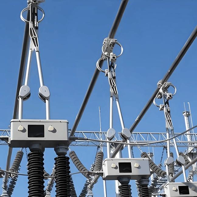
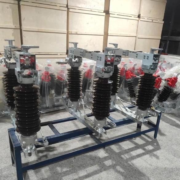
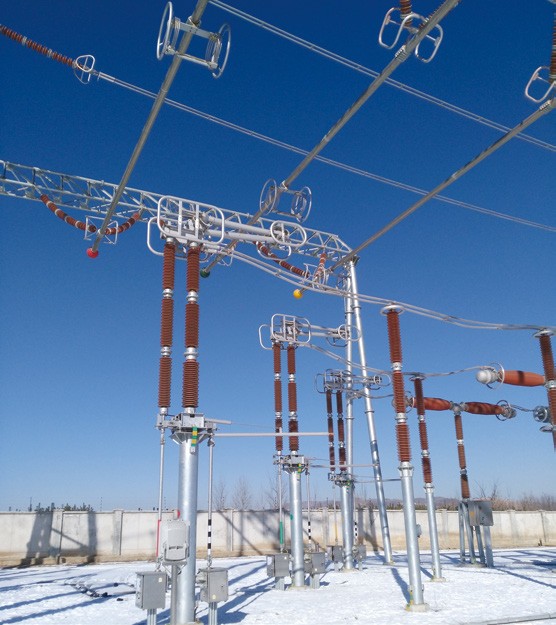
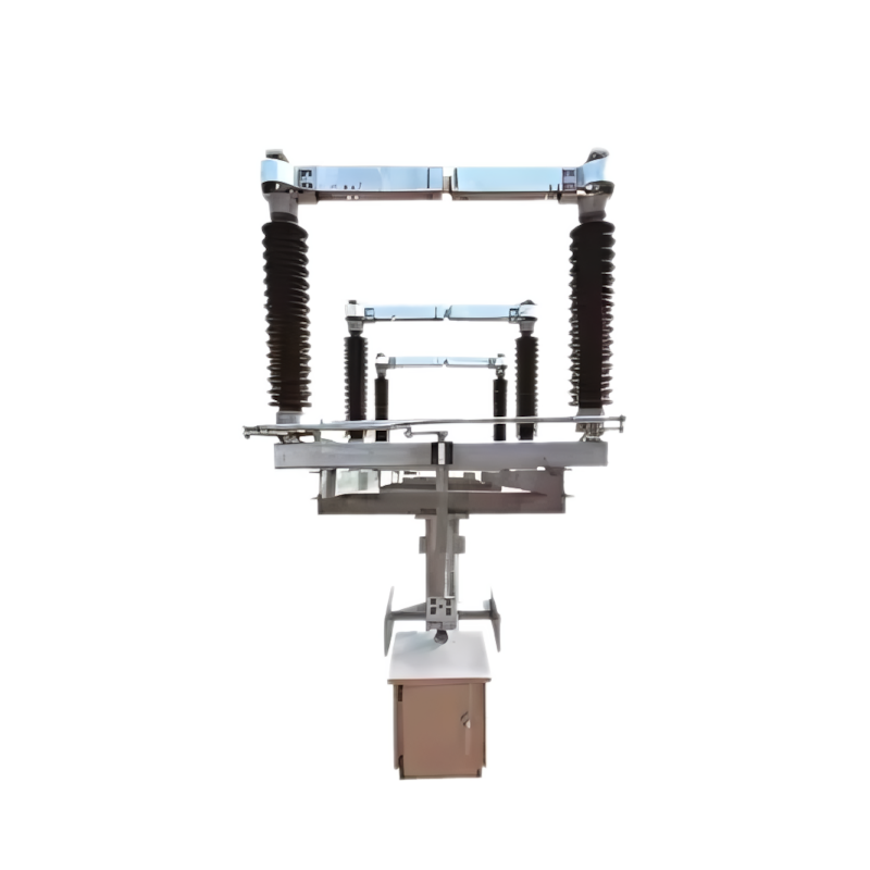
A high-voltage disconnector consists of five parts: support base, conductive part, insulator, transmission mechanism, and operating mechanism. The support base forms the structural foundation of the disconnector, supporting and fixing all other components as an integrated unit. The conductive part ensures efficient current conduction in the circuit. Insulators provide electrical insulation between live parts and grounded parts. The transmission mechanism operates through the insulator to transfer motion to the contacts, enabling opening and closing operations of the disconnector.
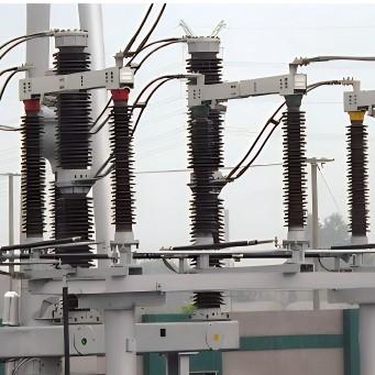
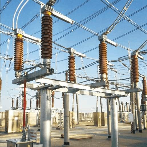
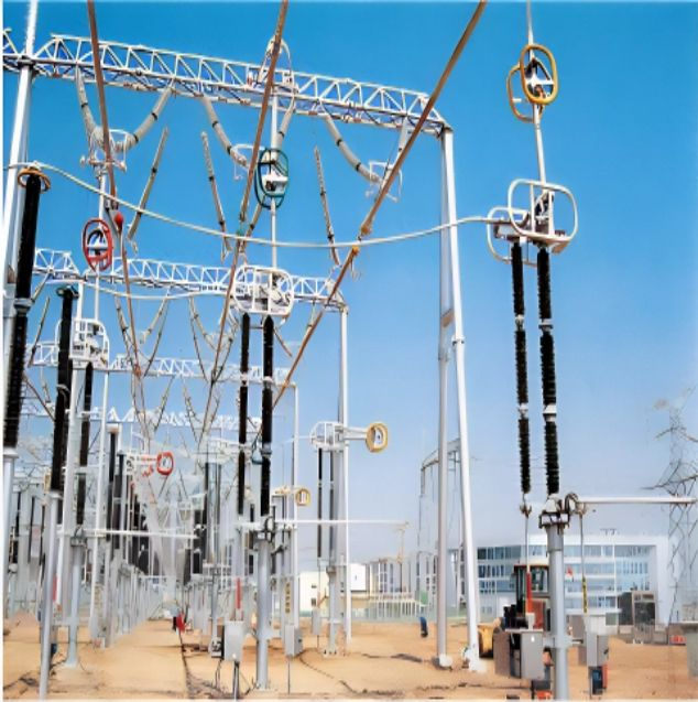
To ensure safety, disconnectors must have a clearly visible open gap, and reliable insulation must exist between all break points. Outdoor disconnectors must reliably perform opening and closing operations under various environmental conditions such as wind, rain, snow, dust, and air pollution. Additionally, a reliable mechanical interlock must be installed between the disconnector and the grounding switch to ensure operators follow safe operational sequences.
For example, high-voltage disconnectors do not require high-speed operation during opening or closing, so they can be directly driven by a motor. In contrast, circuit breakers (high- or low-voltage) are designed to connect or disconnect circuits under load and must operate rapidly—slow or gradual opening/closing would cause arcing. Therefore, circuit breakers use energy-storing motors coupled with springs to store kinetic energy, which is instantly released when needed.
1.2 Classification of Disconnector Corrosion
According to reports, corrosion of high-voltage disconnectors is generally influenced by temperature and humidity, atmospheric pollutants and dust, material properties of components, and manufacturing processes. Metals react with water and oxygen in the atmosphere, and high temperatures or large diurnal temperature variations accelerate this reaction. High humidity and temperature significantly exacerbate metal corrosion, making corrosion particularly severe in such regions.
Atmospheric pollutants contain highly corrosive substances that combine with moisture on metal surfaces to form acidic electrolytes, thereby accelerating electrochemical corrosion. With the rapid development of China’s energy-intensive industries, atmospheric pollution has worsened, acid rain has become more severe, and pollutant levels have increased, creating a vicious cycle that intensifies metal component corrosion.
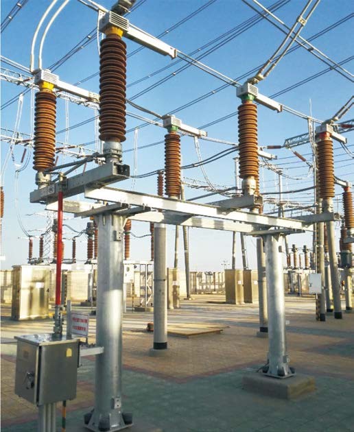
The material itself is another major factor influencing corrosion. Some metals are corrosion-resistant, while others are prone to moisture-induced corrosion; thus, material selection directly determines susceptibility to corrosion. During manufacturing, uneven pressure or heat can cause non-uniform electrode potentials, further accelerating corrosion. For instance, the base beams of disconnectors are often manufactured using hot-dip galvanizing, yet rusting of these beams is common—linked to both operational environmental conditions and manufacturing quality at the factory.
Poor-quality components may undergo electrochemical reactions when exposed to acid rain or salt spray during operation, becoming brittle and cracking under external stress, potentially leading to complete fracture.
1.3 Faults Caused by Corrosion of Disconnector Components
From a minor perspective, corrosion first affects the appearance of the product. Severe rusting is the most frequently reported issue by users, as a rust-stained exterior creates a psychological impression of insecurity. Moreover, corrosion can cause dimensional deformation or reduction in metal components, leading to damage or fracture.
Rotating parts and transmission chains may experience obstruction; any blockage in the mechanism can cause the entire device to jam, rendering it inoperable in severe cases or even causing linkage fractures.
Corrosion also increases contact resistance to some extent. Higher contact resistance leads to heating at contact points, which further accelerates metal oxidation and increases the risk of electrical conduction failure. Prolonged energization under these conditions can result in severe burning of the high-voltage disconnector circuit, potentially triggering electrical safety accidents with irreversible consequences.
2.Theoretical and Practical Analysis of High-Voltage Disconnectors
2.1 Analysis of Component Corrosion
Since the main components of disconnectors are metallic, the causes of disconnector corrosion can largely be understood as causes of metal corrosion. Metal corrosion is influenced by both internal and external factors.
Theoretically, environmental temperature and humidity affect the rate of chemical corrosion of metals. Additionally, the composition of solutions contacting the metal surface and the pH value of those solutions play critical roles. These factors are primarily related to contaminants and PM2.5 particles adhering to the metal surface from the atmosphere.
Internal factors include the physicochemical properties and microstructure of the metal material itself. If a component is made of a corrosion-prone material, extra care must be taken in installation and placement of the disconnector, including careful selection of its installation location. Reactive metals easily lose electrons, leading to material loss or galvanic corrosion. Thus, corrosion of high-voltage disconnectors is unavoidable—it can only be mitigated through maximum protective measures.
For example, connections on both sides of the high-voltage disconnector must be secure and reliable to prevent component corrosion. Connections between metal parts are fundamental and critical and require special attention.
2.2 Theoretical Protection Approaches
From an internal perspective, selecting materials with superior corrosion resistance for metal components—while meeting other performance requirements—provides fundamental protection against corrosion.
From an external perspective, waterproofing and exposure-limiting designs should be implemented to minimize contact between metal parts and humid air or other adverse factors, avoiding issues like water accumulation and excessive atmospheric exposure.
For the overall disconnector, sealing and protective measures should be applied at rotating and transmission bearings to prevent obstruction caused by weather conditions or water ingress. Reliable protective coatings should be applied to surfaces; different coatings should be selected based on metal type, component function, and application environment, always prioritizing safety, operational efficiency, and economic viability.
Conductive substances applied externally to disconnectors must meet component specifications to prevent increased resistance. When overall corrosion becomes severe, the unit should be disassembled for maintenance: contact surfaces cleaned, bolts adjusted, and damaged parts repaired or replaced.
Theoretical protection strategies provide a solid foundation for practical corrosion prevention, with theory and practice being closely interrelated and progressively reinforcing each other.
2.3 Practical Corrosion Protection Techniques
Normally, the stationary contact is connected to the power source, and the moving contact to the load. However, for disconnectors installed in receiving cabinets with cable feed-in, the power source is connected to the moving contact side—a configuration commonly known as “reverse feed.”
During routine maintenance, general inspections should be performed regularly. This constitutes minor or ad-hoc repairs, typically implemented through dynamic management and routine maintenance principles, with targeted repairs scheduled for identified defects or faults.
During major overhauls, disassembly-based maintenance is carried out, involving comprehensive inspection of the equipment with particular focus on metal parts prone to corrosion. Damaged components are either replaced or repaired using appropriate techniques.
Internal mechanisms should be inspected and cleaned periodically. Levers and other transmission linkages should be cleaned, polished, and lubricated. Protective coatings should be reapplied to corroded external surfaces, and additional lubrication and protective devices should be installed at bearings.
These key maintenance procedures must strictly follow the technical specifications and manufacturer’s guidelines to ensure the equipment restores its original technical performance after servicing. Based on the corrosion causes discussed in this paper, routine inspections should be conducted regularly on vulnerable areas, with major overhauls performed at set intervals.
3.Conclusion
High-voltage disconnectors play a significant role in daily life by solving circuit switching problems. However, corrosion of these disconnectors can lead to serious consequences. Therefore, protective measures must be developed through both theoretical research and practical implementation to promote the safe and reliable application of high-voltage disconnectors.