Motor-Operated Mechanism Control System for High-Voltage Disconnectors

High-voltage disconnectors require operating mechanisms with fast response and high output torque. Most current motor-driven mechanisms rely on a series of reduction components, yet motor-operated mechanism control systems effectively meet these requirements.
1. Overview of the Motor-Operated Mechanism Control System for High-Voltage Disconnectors
1.1 Basic Concept
The motor-operated mechanism control system primarily refers to a system that employs a dual-loop PID control strategy to regulate motor winding current and rotational speed, thereby controlling the motion of the mechanism. This ensures that the disconnector contacts reach specified velocities at designated travel points, satisfying the required opening and closing speeds of the disconnector (DS).
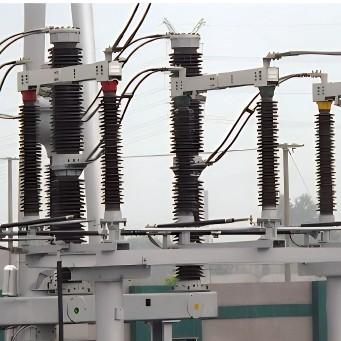
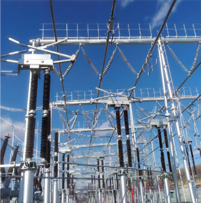
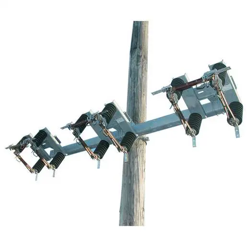
Disconnectors (DS) are the most widely used type of high-voltage switchgear. They effectively establish an insulation gap in power networks, fulfilling critical isolation functions and playing a vital role in line switching and busbar reconfiguration. The primary function of the motor-operated mechanism control system is to automatically monitor voltage and current, isolate high-voltage sections, and ensure safety in high-voltage areas.
1.2 Research Status and Development Trends
(1) Research Status
In high-voltage equipment, motor-operated mechanism control systems are widely adopted due to their simple structure and fast operation, offering ease of control. Research institutions and universities worldwide have clearly differentiated motor-operated mechanisms from spring or hydraulic mechanisms, highlighting their structural simplicity, superior stability, simpler compressed-gas storage methods, and lower operational complexity compared to conventional systems.
Operationally, the system initiates movement through electromagnetic force generated by current-carrying coils and internal current variations. Its application in high-voltage equipment is becoming a trend, with scholars achieving notable progress—continuously refining motor drive technologies and proposing innovative improvements.
While such systems are commonly applied to circuit breakers, research on their use in disconnectors remains limited. Although motors and control components form part of disconnector motor-operated systems, no direct-drive system currently exists that uses a motor to directly actuate contact opening/closing—posing significant operational limitations.
(2) Development Status
Internationally, disconnector manufacturers primarily compete by improving mechanical structures and integrating new materials and technologies to significantly enhance control system performance.
In China, with the steady advancement of the power industry, the number of manufacturers has grown substantially, and numerous large-scale switch control system companies have emerged. Domestic high-voltage disconnector systems are evolving toward higher voltage ratings, greater capacity, enhanced reliability, reduced maintenance, miniaturization, and modular integration:
Higher voltage and capacity align with growing national power supply demands;
Enhanced reliability improves current-carrying capability;
Advanced materials and anti-corrosion techniques increase mechanical flexibility and reduce maintenance needs;
Miniaturization meets increasing demands for system versatility and standardization.
2. System Architecture of the Motor-Operated Mechanism Control System
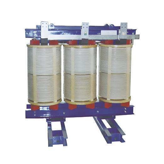
2.1 BLDCM Mechanism System
BLDCM stands for Brushless DC Motor. It rectifies AC power into DC and then uses an inverter to convert it back into controlled AC. Comprising a synchronous motor and a driver, the BLDCM is an electromechanical integrated product that overcomes the drawbacks of brushed DC motors by replacing mechanical commutators with electronic ones.
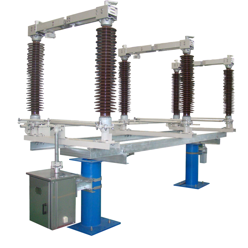
It combines excellent speed regulation with the robustness of AC motors, featuring spark-free commutation, high reliability, and easy maintenance. In standby operating mechanisms for high-voltage disconnectors, BLDCMs are typically equipped with limit switches and directly drive the DS via a crank arm to perform opening/closing operations—effectively addressing traditional issues like excessive linkages and structural complexity.
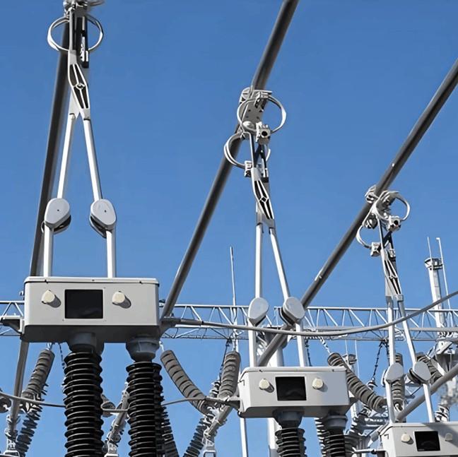
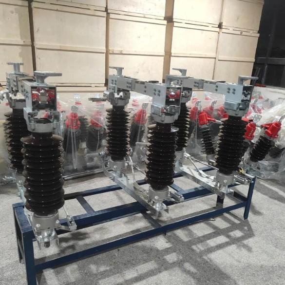
2.2 DS Mechanism System
"DS" denotes the high-voltage disconnector, which provides critical electrical isolation. With a simple structure and high reliability, DS units are extensively used and play a pivotal role in the design, construction, and operation of substations and power plants.
In motor-operated control systems, the DS mechanism typically uses a Digital Signal Processor (DSP) as the core controller to manage overall system functions. The system also includes:
Open/close isolation drive control;
Motor position detection;
Speed detection.
For position detection, the position-sensing circuit provides accurate commutation signals to the logic switch circuit. Speed is measured using an encoder that detects rotor speed, with LED output signals reflecting rotational velocity.
Traditional current detection relies on shunt resistors, which suffer from temperature-induced drift, compromising measurement accuracy. Additionally, insufficient electrical isolation between external and control circuits can amplify voltage surges, threatening system safety.
In the charge/discharge control circuit design, the BLDCM system replaces conventional energy storage with capacitors. The capacitor bank is charged and then isolated from the external power source, enhancing safety and efficiency.
3. Design Improvements for the Motor-Operated Mechanism Control System
3.1 Open/Close Isolation Drive Control Circuit
This circuit controls three-phase winding currents by managing power switching devices and implementing effective strategies for switch trajectory. It mitigates transient overvoltage and switching losses, ensuring safe and stable component operation.
When the switch is off, a capacitor absorbs the turn-off current via a diode during charging. When on, discharge occurs through a resistor. Fast-recovery diodes with rated currents exceeding the main circuit’s rating must be used. To minimize parasitic inductance, high-frequency, high-performance snubber capacitors are recommended.
3.2 Motor Position Detection Circuit
This design accurately determines rotor magnetic pole positions, enabling precise commutation control of stator windings. Three Hall-effect sensors are fixed onto a Hall disk, while a circular permanent magnet simulates the motor’s magnetic field for enhanced positional accuracy. As the magnet rotates, Hall sensor outputs vary distinctly, allowing precise electronic rotor positioning.
3.3 Speed Detection Circuit
An optical rotary encoder—comprising infrared LED–phototransistor optocouplers and a slotted shutter disk—is used to measure rotor speed. The optocouplers are evenly distributed in a circular pattern. The shutter disk, positioned between LEDs and phototransistors, contains windows that modulate light transmission as it rotates. The resulting pulsed output signal enables calculation of rotor acceleration and speed.
3.4 Current Detection Circuit
Traditional shunt-resistor-based detection suffers from thermal drift and poor accuracy. Moreover, inadequate electrical isolation between power and control circuits risks high-voltage transients damaging sensitive electronics.
To address this, the improved design employs an electrically isolated Hall-effect current sensor. During operation, the alternating current in motor windings is sensed, and a summing amplifier processes the sensor output. After proportional scaling, a safe, isolated current signal is obtained.
3.5 Capacitor Charge/Discharge Control Circuit
The BLDCM system replaces conventional energy storage with capacitor-based solutions, significantly improving efficiency and simplifying charge/discharge control. A digital signal processor continuously monitors capacitor voltage and terminates charging only when operational thresholds are met. This design excels in energy management and signal acquisition, enabling precise circuit control.
4. Conclusion
The motor-operated mechanism control system for high-voltage disconnectors represents a strategic response to rising power demands and a commitment to safeguarding modern living standards. By effectively resolving longstanding limitations of traditional disconnectors, this system plays a pivotal role in advancing the reliability, efficiency, and intelligence of power infrastructure.