Transformer Neutral Grounding Disconnector: Function, Principle, Structure, Operation, and Maintenance
A transformer neutral grounding disconnector is an electrical device used to isolate the neutral point of a power transformer. Its primary purpose is to protect both the transformer and the overall power system, ensuring safe and stable operation.
Transformer Protection
One of the key roles of the neutral grounding disconnector is to safeguard the transformer. During operation, abnormal conditions—such as overloads, short circuits, or lightning strikes—can cause unusual currents or voltages within the transformer. If these anomalies are not promptly isolated, they may cause severe damage. The neutral disconnector enables rapid disconnection of the transformer’s neutral point under fault conditions, thereby protecting the transformer from harm.
Power System Protection
The disconnector also contributes to the stability of the entire power system. As a critical component, any transformer failure can jeopardize system-wide reliability. By isolating the neutral point during faults, the disconnector helps prevent fault propagation and maintains the safety and stability of the grid.
Facilitation of Maintenance and Inspection
During maintenance or inspection, the transformer must be fully isolated from the power system to ensure personnel safety. The neutral grounding disconnector provides a reliable means to achieve this isolation, making maintenance procedures safer and more efficient.
Prevention of Resonance Phenomena
In certain configurations, the transformer neutral may interact with other system components, leading to resonance that causes dangerous voltage or current oscillations. Proper use of the neutral disconnector can eliminate such resonant conditions, enhancing system stability.
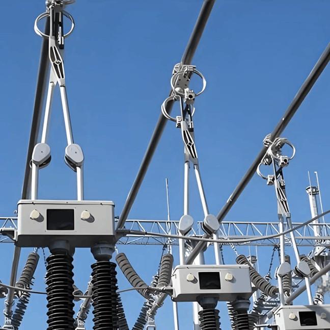
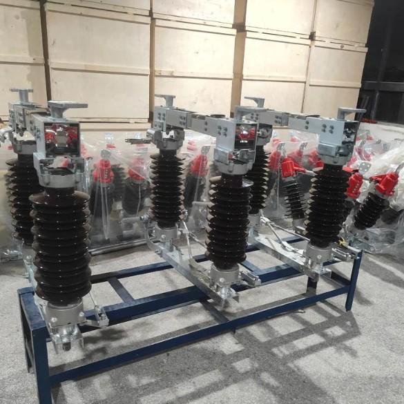
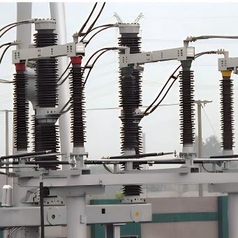
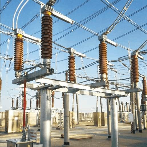
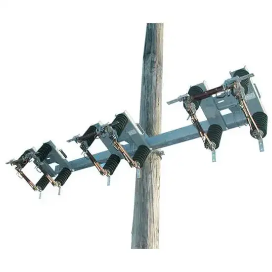
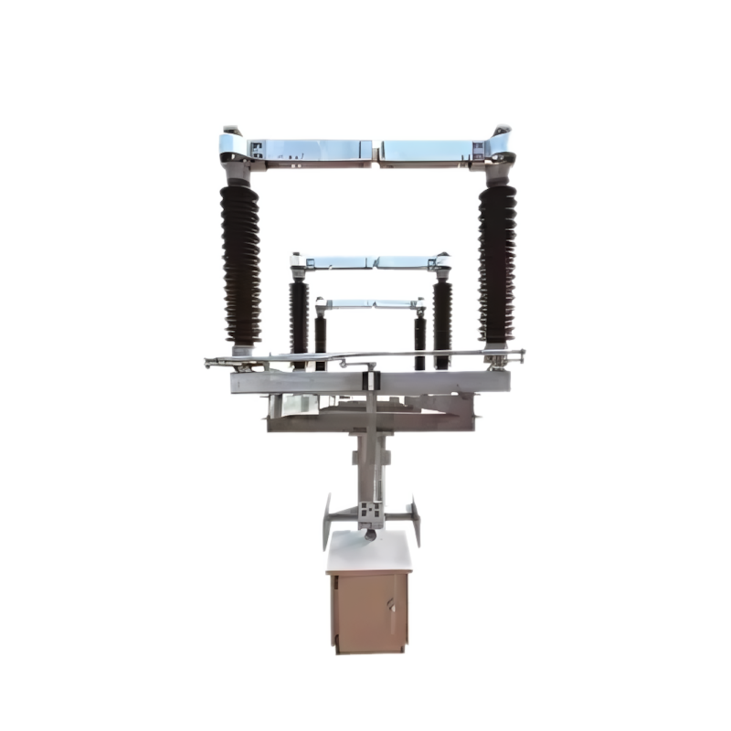
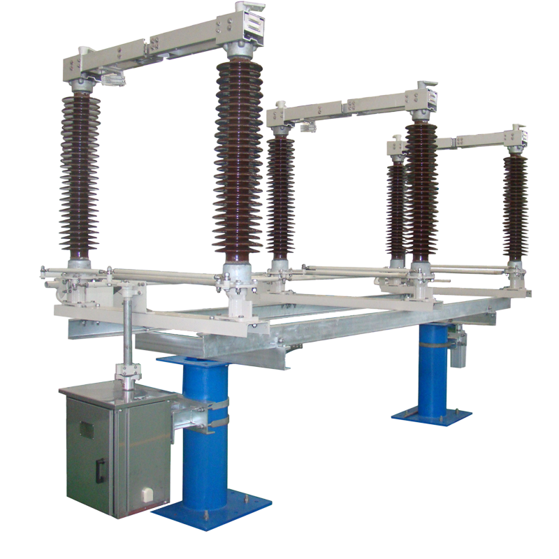
The transformer neutral grounding disconnector operates via mechanical or electromagnetic actuation mechanisms to connect or isolate the transformer’s neutral point. It consists of the following main components:
Operating Mechanism: The core component responsible for opening and closing the switch. It can be manual, electric, pneumatic, or hydraulic.
Contact System: Comprising movable and fixed contacts, this system establishes or breaks the electrical connection at the neutral point. The moving contact is linked to the operating mechanism, while the stationary contact is mounted on the housing.
Insulation System: Made from high-performance materials (e.g., epoxy resin, ceramic), it ensures effective electrical isolation of the neutral point.
Enclosure: Typically constructed from metal (e.g., aluminum alloy or stainless steel), the enclosure protects internal components from environmental factors.
During operation, the control signal or manual command activates the operating mechanism, which drives the moving contact to engage with or separate from the fixed contact—thereby connecting or disconnecting the transformer neutral.
Compact Design: Small footprint, easy to install and maintain.
Simple Operation: Intuitive mechanism enables quick and reliable switching.
Excellent Insulation: High-quality insulating materials ensure robust dielectric performance.
High Reliability: Optimized contact and drive systems guarantee long-term stable operation.
Easy Maintenance: Modular design allows convenient inspection and component replacement.
Ensure the transformer is completely de-energized before operating the neutral disconnector to prevent electric shock.
Follow established operating procedures strictly to avoid misoperation.
After operation, verify the actual open/closed status of the disconnector to confirm proper isolation of the neutral point.
Always use the neutral disconnector to isolate the transformer during maintenance to ensure worker safety.
After maintenance, reconnect the neutral point using the disconnector and perform necessary tests to confirm normal transformer operation.
Regularly inspect mechanical components (e.g., operating mechanism, contacts) for wear or malfunction.
Check the insulation system periodically—including insulating materials and clearance distances—to ensure integrity.
Clean the enclosure and internal parts routinely to remove dust and contaminants that could impair performance or cause tracking.