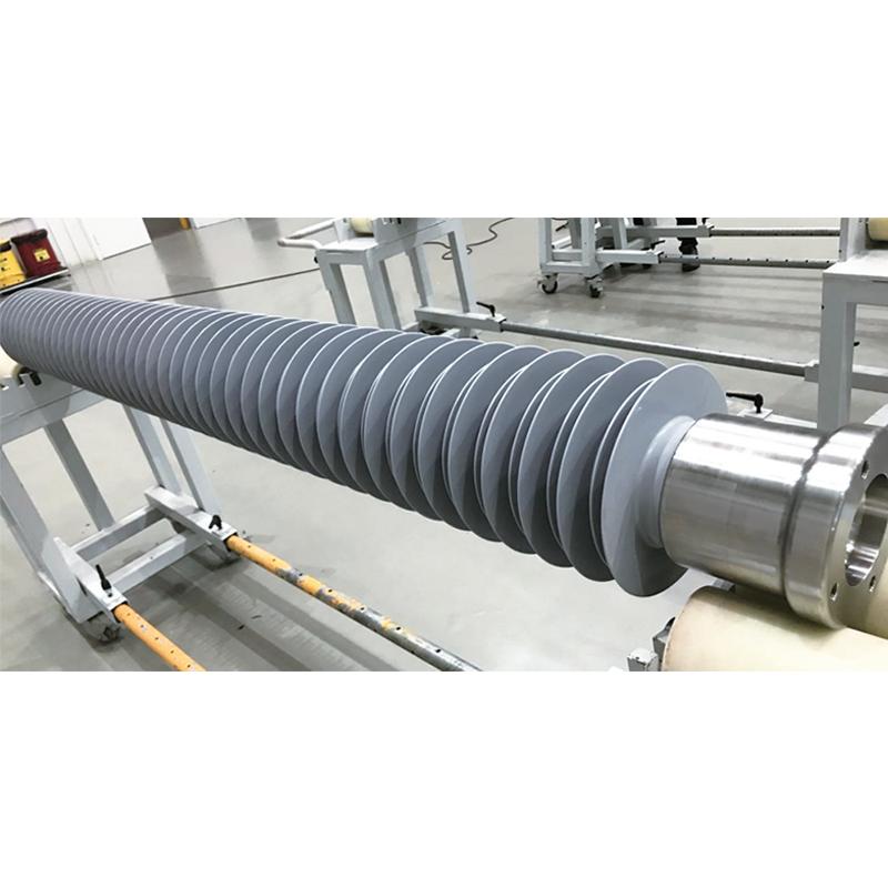
35kV-1100kV Ultra high voltage pillar composite insulator
Key attributes
| Brand | Switchgear parts |
| Model NO. | 35kV-1100kV Ultra high voltage pillar composite insulator |
| Rated voltage | 40.5kV |
| 额定弯曲负荷 | 20kN |
| Series | FZSW |
Product descriptions from the supplier
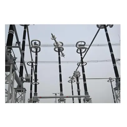
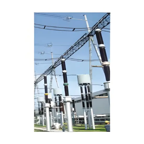
The composite insulator for power system is composed of three main components: core body (FRP), silicone rubber umbrella sleeve (HTV), and end flange (precision cast steel, welded steel, stainless steel). The two end flanges are assembled with the core body by crimping. This product has excellent anti fouling flashover performance, anti brittle fracture, excellent insulation performance, light weight, easy installation and transportation, safety and reliability, and other advantages. Pillar composite insulators are used in electrical equipment such as substations and converter stations with AC voltage ranging from 40.5kV to 1100kV and DC voltage ranging from ± 100kV to ± 800kV. The main application products include reactor supports, high-voltage isolation switch insulation pillars, busbar supports, and insulation supports for other high-voltage equipment.
Product Features
a) Core: Using epoxy resin glass fiber pull rods as internal insulation support, it has excellent seismic performance and can prevent brittle fracture;
b) Silicone rubber umbrella cover: injection molded as a whole, optimized umbrella design, improved crawling distance effectiveness and product pollution flashover voltage;
c) End flange: The flange is assembled using crimping technology, which ensures stable and reliable mechanical performance and high production efficiency;
d) The overall weight of the product is lighter than that of porcelain insulators, making it easier to install, with a short production cycle and high quality stability.
Product Specifications
| Insulator Model | Rated Voltage (kV) | Maximum Operating Voltage (kV) | Mechanical Load (≥) | Structural Height (≥ mm) | Arc Flash Distance (≥ mm) | Minimum Nominal Creepage Distance (≥ mm) | Power Frequency/DC Wet Withstand Voltage (≥ kV) | Lightning Impulse Withstand Voltage (≥ kV) | Switching Impulse Withstand Voltage (≥ kV) | Core Diameter (mm) | Number of Sections | |||
|---|---|---|---|---|---|---|---|---|---|---|---|---|---|---|
| SCL (kN) | SCOL (kN) | STOL (kN·m) | STL (kN) | |||||||||||
| FZSW-40.5/20 | 35 | 40.5 | 20 | 150 | 4 | 50 | 680 | 510 | 1900 | 130 | 250 | / | 90 | 1 |
| FZSW-72.5/15 | 66 | 72.5 | 15 | 150 | 10 | 10 | 850 | 680 | 2600 | 140 | 325 | / | 90 | 1 |
| FZSW-126/8 | 110 | 126 | 8 | 150 | 4 | 100 | 1250 | 1080 | 4300 | 230 | 550 | / | 90 | 1 |
| FZSW-±100/20 | ±100 | ±120 | 20 | 220 | 10 | 100 | 1640 | 1400 | 3500 | ±200 | (650) 350 | / | 110 | 1 |
| FZSW-220/24 | 220 | 252 | 24 | / | 10 | / | 2295 | 2027 | 7040 | 395 | 1050 | / | 110 | 1 |
| FZSW-252/22 | 220 | 252 | 22 | 350 | 10 | 100 | 2400 | 2130 | 9000 | 460 | 1050 | 850 | 120 | 1 |
| FZSW-363/20 | 330 | 363 | 20 | 350 | 10 | 100 | 3000 | 2700 | 10000 | 560 | 1100 | 852 | 150 | 1 |
| FZSW-±300/30 | ±300 | ±306 | 30 | 350 | 10 | 100 | 3280 | 2860 | 7200 | 570/±560 | 1080 | 852 | 160 | 1 |
| FZSW-±400/25 | ±400 | ±480 | 25 | 400 | 10 | 100 | 5600 | 5180 | 14000 | 1050/±620 | 1350 | 1250 | 180 | 1 |
| FZSW-550/16 | 500 | 550 | 16 | 500 | 10 | 100 | 4600 | 4340 | 18900 | 740 | 2250 | 1240 | 180 | 1 |
| FZSW-±660/30 | ±660 | / | 30 | 500 | 10 | 100 | 8000 | 7200 | 37000 | 960 | 2100 | 1425 | 220 | 2 |
| FZSW-±700/30 | ±700 | ±740 | 30 | 400 | 10 | 200 | 9000 | 8240 | 26000 | 1100/±1200 | 2150 | 1800 | 220 | 2 |
| FZSW-±700/12.5 | ±700 | ±740 | 12.5 | 500 | 10 | 100 | 10000 | 9095 | 38700 | 1050 | 2400 | 1550 | 220 | 3 |
| FZSW-±800/16 | ±800 | ±816 | 16 | 500 | 10 | 100 | 12270 | 10675 | 42750 | 1620 | 2750 | 1900 | 280 | 5 |
| FZSW-±1100/16 | ±1100 | / | 16 | 500 | 10 | 100 | 15773 | 13818 | 55000 | / | 2550 | 2100 | 280 | 6 |
Suitable for 35-110kV substations, overhead transmission lines, switchgear, and railway electrification systems. Core parameters: Rated voltage 35/66/110kV, rated mechanical load ≥10kN, creepage distance 25-31mm/kV (customizable for heavy pollution), operating temperature -40℃~+80℃. Ideal for high-altitude, coastal, industrial heavy pollution, and other harsh environments.
Key advantages include: ① Lightweight (60% lighter than ceramic ones), simplifying transportation and installation; ② Excellent hydrophobicity and self-cleaning performance, avoiding pollution flashover even in heavy pollution areas; ③ Good impact resistance and flexibility, not easy to break; ④ Low maintenance demand, with a service life of over 30 years; ⑤ Environmentally friendly manufacturing process and recyclable materials.
As a key insulation component for power systems, it mainly realizes two core functions: ① Electrical insulation between high-voltage conductors and grounded structures to prevent leakage current; ② Mechanical support for conductors and equipment, ensuring stable operation of 35-110kV substations, power transmission lines, and switchgear under various environmental conditions.

Related Products
-
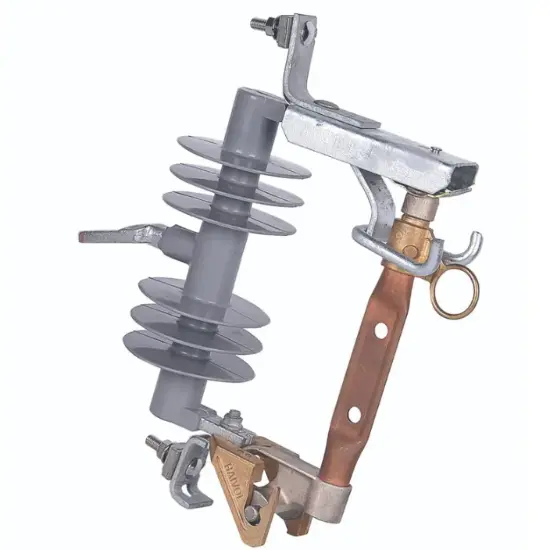
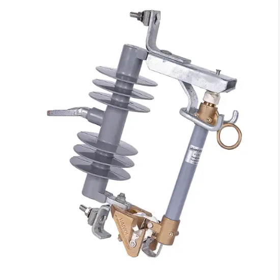
Isolation Type Drop Out Fuse
-
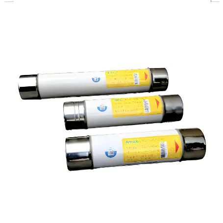
High voltage current limiting fuse for oil immersed transformer protection
-
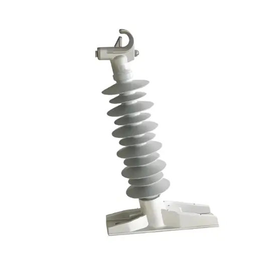
12kV 24kV 35kV 72.5kV Composite Post Insulator
-
Silicone Rubber Standard Drop Out Fuse
-
The high-voltage disconnect switch uses rod-shaped porcelain insulators
-
IEC series rod-shaped porcelain insulators
-
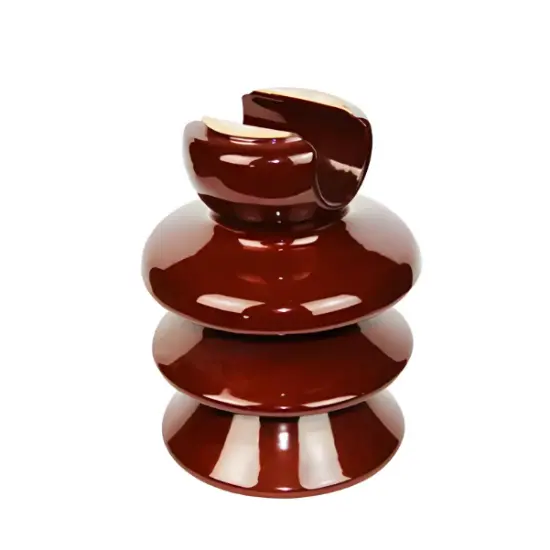
Pin Type Insulator 11kV 22kV 33kV
Related Knowledges
-
 Main Transformer Accidents and Light Gas Operation Issues1. Accident Record (March 19, 2019)At 16:13 on March 19, 2019, the monitoring background reported a light gas action of No. 3 main transformer. In accordance with the Code for Operation of Power Transformers (DL/T572-2010), operation and maintenance (O&M) personnel inspected the on-site condition of No. 3 main transformer.On-site confirmation: The WBH non-electrical protection panel of No. 3 main transformer reported a Phase B light gas action of the transformer body, and the reset was ineff02/05/2026
 -
 Faults and Handling of Single-phase Grounding in 10kV Distribution LinesCharacteristics and Detection Devices for Single-Phase Ground Faults1. Characteristics of Single-Phase Ground FaultsCentral Alarm Signals:The warning bell rings, and the indicator lamp labeled “Ground Fault on [X] kV Bus Section [Y]” illuminates. In systems with a Petersen coil (arc suppression coil) grounding the neutral point, the “Petersen Coil Operated” indicator also lights up.Insulation Monitoring Voltmeter Indications:The voltage of the faulted phase decreases (in01/30/2026
 -
 Neutral point grounding operation mode for 110kV~220kV power grid transformersThe arrangement of neutral point grounding operation modes for 110kV~220kV power grid transformers shall meet the insulation withstand requirements of transformer neutral points, and shall also strive to keep the zero-sequence impedance of substations basically unchanged, while ensuring that the zero-sequence comprehensive impedance at any short-circuit point in the system does not exceed three times the positive-sequence comprehensive impedance.For 220kV and 110kV transformers in new constructi01/29/2026
 -
 Why Do Substations Use Stones, Gravel, Pebbles, and Crushed Rock?Why Do Substations Use Stones, Gravel, Pebbles, and Crushed Rock?In substations, equipment such as power and distribution transformers, transmission lines, voltage transformers, current transformers, and disconnect switches all require grounding. Beyond grounding, we will now explore in depth why gravel and crushed stone are commonly used in substations. Though they appear ordinary, these stones play a critical safety and functional role.In substation grounding design—especially when multiple gr01/29/2026
 -
 Why Must a Transformer Core Be Grounded at Only One Point? Isn't Multi-Point Grounding More Reliable?Why Does the Transformer Core Need to Be Grounded?During operation, the transformer core, along with the metal structures, parts, and components that fix the core and windings, are all situated in a strong electric field. Under the influence of this electric field, they acquire a relatively high potential with respect to ground. If the core is not grounded, a potential difference will exist between the core and the grounded clamping structures and tank, which may lead to intermittent discharge.I01/29/2026
 -
 Understanding Transformer Neutral GroundingI. What is a Neutral Point?In transformers and generators, the neutral point is a specific point in the winding where the absolute voltage between this point and each external terminal is equal. In the diagram below, pointOrepresents the neutral point.II. Why Does the Neutral Point Need Grounding?The electrical connection method between the neutral point and earth in a three-phase AC power system is called theneutral grounding method. This grounding method directly affects:The safety, reliabilit01/29/2026


