• Product
  • Suppliers
  • Manufacturers
  • Solutions
  • Free tools
  • Knowledges
  • Experts
  • Communities
Search


500kV Series Porcelain-Housed Metal Oxide Surge Arresters

  • 500kV Series Porcelain-Housed Metal Oxide Surge Arresters

Key attributes

Brand Wone Store
Model NO. 500kV Series Porcelain-Housed Metal Oxide Surge Arresters
Rated voltage 420kV
Rated frequency 50/60Hz
Series Y20W

Product descriptions from the supplier

Description

Description 

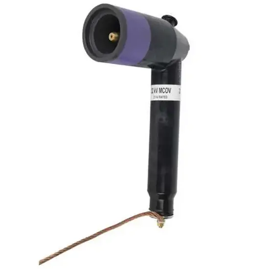
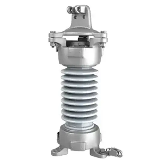
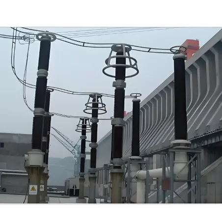
500kV Series Porcelain-Housed Metal Oxide Surge Arresters are critical protective devices designed for ultra-high voltage (UHV) power systems, specifically 500kV transmission lines, substations, and associated equipment (e.g., transformers, circuit breakers). Their core function is to limit transient overvoltages caused by lightning strikes, switching operations, or faults, diverting excessive surge currents to the ground while maintaining stable voltage levels during normal operation. Encased in high-strength porcelain housings, they combine robust mechanical protection with advanced metal oxide varistor (MOV) technology, ensuring reliable defense for 500kV grid infrastructure against electrical surges that could cause equipment damage or power outages.

Features 

  • Superior Surge Handling Capacity: Equipped with multi-layer metal oxide varistors (MOVs) with high non-linear resistance characteristics. They can withstand extreme surge currents (up to several hundred kA) from lightning or switching events, rapidly clamping overvoltages to safe levels.

  • Durable Porcelain Housing: The outer porcelain enclosure is weather-resistant, corrosion-proof, and mechanically strong, designed to withstand harsh environmental conditions (e.g., high humidity, pollution, extreme temperatures, and seismic activity). It provides insulation and physical protection for internal MOV components.

  • Low Leakage Current: Optimized MOV formulation minimizes leakage current during normal operation (typically <100&mu;A), reducing energy loss and thermal stress. This ensures long-term stability and extends service life (up to 20+ years).

  • Self-Recovery Performance: After diverting a surge, the arresters quickly return to their high-resistance state, preventing continuous current flow and avoiding interference with normal grid operation. This self-recovery capability eliminates the need for manual resetting.

  • Series Configuration Adaptability: Designed for series connection to match the 500kV voltage level, with uniform voltage distribution across units. Integrated grading rings or capacitors ensure balanced electrical stress, enhancing overall system reliability.

  • Easy Installation & Maintenance: Lightweight compared to traditional arresters, with standardized mounting flanges for compatibility with 500kV substation structures. Many models include built-in monitoring ports for leakage current or temperature checks, facilitating predictive maintenance.

  • Compliance with International Standards: Meets IEC 60099-4, ANSI/IEEE C62.11, and other global standards for surge arresters, ensuring compatibility with 500kV grids worldwide and adherence to safety and performance requirements.

Basic parameters

Model


Arrester

System

Arrester Continuous

DC 1mA

Switching Impulse

Nominal Impulse

Steep - Front Impulse

2ms Square Wave

Nominal

Rated Voltage

Nominal Voltage

Operating Voltage

Reference Voltage

Voltage Residual

Voltage Residual

Current Residual

Current - Withstand Capacity

Creepage Distance

kV

kV

kV

kV

kV

kV

kV

A

mm

(RMS Value)

(RMS Value)

(RMS Value)

Not Less Than

Not Greater Than

Not Greater Than

Not Greater Than

20 Times


Peak Value

Peak Value

Peak Value

Peak Value


Y20W1-420/1006W

420

500

318

565

825

1006

1106

1500

15300

Y20W1-444/1063W

444

500

324

597

871

1063

1160

1500

15300

Y20W1-468/1166W

468

500

330

630

918

1120

1255

1500

15300

Y20W1-420/1006W

420

500

318

565

825

1006

1106

2000

15300

Y20W1-444/1063W

444

500

324

597

871

1063

1160

2000

15300

Y20W1-468/1120W

468

500

330

630

918

1120

1255

2000

15300

Y20W1-420/1006W

420

500

318

565

825

1006

1106

2500

18000

Y20W1-444/1063W

444

500

324

597

871

1063

1160

2500

18000

Y20W1-468/1166W

468

500

330

630

918

1120

1255

2500

18000

Y20W1-420/1006W

420

500

318

565

825

1006

1106

1500

18900

Y20W1-444/1063W

444

500

324

597

871

1063

1160

1500

18900

Y20W1-468/1166W

468

500

330

630

918

1120

1255

1500

18900

Y20W1-420/1006W

420

500

318

565

825

1006

1106

2000

18900

Y20W1-444/1063W

468

500

330

630

918

1120

1255

2000

18900

Y20W1-468/1166W

468

500

330

630

918

1120

1255

2000

18900

Know your supplier
Online store
On-time delivery rate
Response time
100.0%
≤4h
Company overview
Workplace: 1000m² Total staff: Highest Annual Export(usD): 300000000
Workplace: 1000m²
Total staff:
Highest Annual Export(usD): 300000000
Services
Business Type: Sales
Main Categories: Wire cable/High Voltage Electrical Apparatus/Low Voltage Electrical Apparatus/Instrument meters/New energy/Tester/Integrated Electrical Equipment/Production equipment/Generator/Electrical fittings/Instrument Transformer/Equipment Parts
Whole life care manager
Whole-life care management services for equipment procurement, use, maintenance, and after-sales, ensuring safe operation of electrical equipment, continuous control, and worry-free electricity consumption.
The equipment supplier has passed platform qualification certification and technical evaluation, ensuring compliance, professionalism, and reliability from the source.

Related Products

Related Knowledges

  • Faults and Handling of Single-phase Grounding in 10kV Distribution Lines
    Characteristics and Detection Devices for Single-Phase Ground Faults1. Characteristics of Single-Phase Ground FaultsCentral Alarm Signals:The warning bell rings, and the indicator lamp labeled “Ground Fault on [X] kV Bus Section [Y]” illuminates. In systems with a Petersen coil (arc suppression coil) grounding the neutral point, the “Petersen Coil Operated” indicator also lights up.Insulation Monitoring Voltmeter Indications:The voltage of the faulted phase decreases (in
    01/30/2026
  • Neutral point grounding operation mode for 110kV~220kV power grid transformers
    The arrangement of neutral point grounding operation modes for 110kV~220kV power grid transformers shall meet the insulation withstand requirements of transformer neutral points, and shall also strive to keep the zero-sequence impedance of substations basically unchanged, while ensuring that the zero-sequence comprehensive impedance at any short-circuit point in the system does not exceed three times the positive-sequence comprehensive impedance.For 220kV and 110kV transformers in new constructi
    01/29/2026
  • Why Do Substations Use Stones, Gravel, Pebbles, and Crushed Rock?
    Why Do Substations Use Stones, Gravel, Pebbles, and Crushed Rock?In substations, equipment such as power and distribution transformers, transmission lines, voltage transformers, current transformers, and disconnect switches all require grounding. Beyond grounding, we will now explore in depth why gravel and crushed stone are commonly used in substations. Though they appear ordinary, these stones play a critical safety and functional role.In substation grounding design—especially when multiple gr
    01/29/2026
  • Why Must a Transformer Core Be Grounded at Only One Point? Isn't Multi-Point Grounding More Reliable?
    Why Does the Transformer Core Need to Be Grounded?During operation, the transformer core, along with the metal structures, parts, and components that fix the core and windings, are all situated in a strong electric field. Under the influence of this electric field, they acquire a relatively high potential with respect to ground. If the core is not grounded, a potential difference will exist between the core and the grounded clamping structures and tank, which may lead to intermittent discharge.I
    01/29/2026
  • Understanding Transformer Neutral Grounding
    I. What is a Neutral Point?In transformers and generators, the neutral point is a specific point in the winding where the absolute voltage between this point and each external terminal is equal. In the diagram below, pointOrepresents the neutral point.II. Why Does the Neutral Point Need Grounding?The electrical connection method between the neutral point and earth in a three-phase AC power system is called theneutral grounding method. This grounding method directly affects:The safety, reliabilit
    01/29/2026
  • What’s the Difference Between Rectifier Transformers and Power Transformers?
    What is a Rectifier Transformer?"Power conversion" is a general term encompassing rectification, inversion, and frequency conversion, with rectification being the most widely used among them. Rectifier equipment converts input AC power into DC output through rectification and filtering. A rectifier transformer serves as the power supply transformer for such rectifier equipment. In industrial applications, most DC power supplies are obtained by combining a rectifier transformer with rectifier equ
    01/29/2026

Related Solutions

  • Dedicated Vacuum Contactor Solution for Port Shore Power Systems
    I. Background and Challenges​Shore power systems have become core technical equipment for ports to reduce carbon emissions and noise pollution. However, these systems face two major challenges in the harsh operational environment of ports:​Severe Environmental Corrosion: High humidity and salt spray in port areas cause serious corrosion to metal components and enclosures of electrical equipment, significantly impacting electrical lifespan and operational reliability.​High Switching Requirements:
    09/13/2025
  • ABB Vacuum Contactor KC2 Power Supply System Technical Transformation Plan
    Issue Overview​The 10kV air compressor starting system of a company utilizes the ABB vacuum contactor KC2 as the control component for the operating circuit. The dedicated wide-voltage power supply module paired with this contactor presents the following issues:​Frequent failures: The power supply module fails to properly transition the voltage from 300V to 12V, resulting in fuse blowouts.​Poor heat dissipation: Enclosed installation of the module leads to insufficient heat dissipation, acceler
    09/13/2025
  • Solution for Medium-Voltage Motor Control and Protection Using Vacuum Contactor-Fuse (VCF) in a Coal Conveying System
    1.Project BackgroundA coal conveying system comprises 15 belt conveyors driven by medium-voltage motors. The system operates under complex conditions, with motors often subjected to heavy loads and frequent starts. To address these challenges and achieve effective control and reliable protection during motor startup, the project comprehensively adopts Vacuum Contactor-Fuse (VCF) combination devices for the 6kV medium-voltage motor power distribution. This solution details the technical features,
    09/13/2025
Haven't found the right supplier yet? Let matching verified suppliers find you. Get Quotation Now
Haven't found the right supplier yet? Let matching verified suppliers find you.
Get Quotation Now
Send inquiry
+86
Click to upload file
Download
Get the IEE Business Application
Use the IEE-Business app to find equipment, obtain solutions, connect with experts, and participate in industry collaboration anytime, anywhere—fully supporting the development of your power projects and business.