• Product
  • Suppliers
  • Manufacturers
  • Solutions
  • Free tools
  • Knowledges
  • Experts
  • Communities
Search


cooper power series 150 A externally operated tap-changer switch

  • cooper power series 150 A externally operated tap-changer switch
  • cooper power series 150 A externally operated tap-changer switch

Key attributes

Brand Transformer Parts
Model NO. cooper power series 150 A externally operated tap-changer switch
Rated voltage 35kV
Rated normal current 150A
Phases Three phase
Power frequency withstand voltage 50kV/min
Number of interfaces 7-Position
installation contact type "T" Handle
Series cooper power series

Product descriptions from the supplier

Description

General
The hazards associated with manual internal tap changing of distribution transformers with its Cooper Power™ series 150 A externally operated tap-changer switch because line crews need not be exposed to high voltage conductors and hot transformer fluids.

Tap-changer switches eliminate the need to dismount pole-type transformers for voltage adjustment and exposure of the transformer tank interior to contamination. They are designed for use in distribution transformers filled with transformer oil, Envirotemp™ FR3™ fluid, or an approved equivalent.

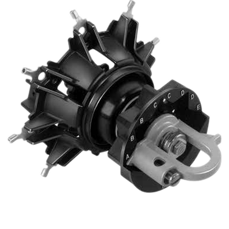
Tap-changer switches are available with five or seven switch positions, and for sidewall- or covermounted applications. The switch body, rotor, and shaft are made of a high-strength glass-filled polyester material. The operating shaft is sealed against leakage by two high temperature resistant Viton® O-rings. The tapered gasket seal controls compression and prevents overtightening.

The tap-changer switch is keyed to the tank wall to prevent switch body movement during switching. Switch positions are easily changed by pulling out the spring-loaded handle, turning it to the desired position, and allowing the pointer to drop into the slotted index plate. The pad-lockable operating handle provides greater leverage, can be operated by hand and has a lock screw. The easy to read raised white letters on the black index plate clearly identify switch position.
All copper, low resistance, pinch-type contacts provide self-wiping connections. For ease of connection, bolt tabs, bolt tabs with 1/4-20 stud, 16-14 AWG, 12-10 AWG, 8 AWG or 6 AWG crimp terminals are available. Switches with crimp terminals have additional inboard tapped holes for making separate ring tongue terminal connections without changing switch contacts. All terminals have hex recesses to hold 7/16 inch hex bolt heads of standard 1/4 inch hardware for fast, easy connections.


If you need to know about more parameters, Please check the catalog data.↓

Or you are welcome to contact us.→


Documentation Resource Library
Restricted
cooper power series 150 A externally operated tap-changer switch catalog data
Operation manual
English
Consulting
Consulting
Know your supplier
Online store
On-time delivery rate
Response time
100.0%
≤4h
Company overview
Workplace: 1000m² Total staff: Highest Annual Export(usD): 300000000
Workplace: 1000m²
Total staff:
Highest Annual Export(usD): 300000000
Services
Business Type: Design/Sales
Main Categories: Electrical fittings
Whole life care manager
Whole-life care management services for equipment procurement, use, maintenance, and after-sales, ensuring safe operation of electrical equipment, continuous control, and worry-free electricity consumption.
The equipment supplier has passed platform qualification certification and technical evaluation, ensuring compliance, professionalism, and reliability from the source.

Related Products

Related Knowledges

  • Faults and Handling of Single-phase Grounding in 10kV Distribution Lines
    Characteristics and Detection Devices for Single-Phase Ground Faults1. Characteristics of Single-Phase Ground FaultsCentral Alarm Signals:The warning bell rings, and the indicator lamp labeled “Ground Fault on [X] kV Bus Section [Y]” illuminates. In systems with a Petersen coil (arc suppression coil) grounding the neutral point, the “Petersen Coil Operated” indicator also lights up.Insulation Monitoring Voltmeter Indications:The voltage of the faulted phase decreases (in
    01/30/2026
  • Neutral point grounding operation mode for 110kV~220kV power grid transformers
    The arrangement of neutral point grounding operation modes for 110kV~220kV power grid transformers shall meet the insulation withstand requirements of transformer neutral points, and shall also strive to keep the zero-sequence impedance of substations basically unchanged, while ensuring that the zero-sequence comprehensive impedance at any short-circuit point in the system does not exceed three times the positive-sequence comprehensive impedance.For 220kV and 110kV transformers in new constructi
    01/29/2026
  • Why Do Substations Use Stones, Gravel, Pebbles, and Crushed Rock?
    Why Do Substations Use Stones, Gravel, Pebbles, and Crushed Rock?In substations, equipment such as power and distribution transformers, transmission lines, voltage transformers, current transformers, and disconnect switches all require grounding. Beyond grounding, we will now explore in depth why gravel and crushed stone are commonly used in substations. Though they appear ordinary, these stones play a critical safety and functional role.In substation grounding design—especially when multiple gr
    01/29/2026
  • Why Must a Transformer Core Be Grounded at Only One Point? Isn't Multi-Point Grounding More Reliable?
    Why Does the Transformer Core Need to Be Grounded?During operation, the transformer core, along with the metal structures, parts, and components that fix the core and windings, are all situated in a strong electric field. Under the influence of this electric field, they acquire a relatively high potential with respect to ground. If the core is not grounded, a potential difference will exist between the core and the grounded clamping structures and tank, which may lead to intermittent discharge.I
    01/29/2026
  • Understanding Transformer Neutral Grounding
    I. What is a Neutral Point?In transformers and generators, the neutral point is a specific point in the winding where the absolute voltage between this point and each external terminal is equal. In the diagram below, pointOrepresents the neutral point.II. Why Does the Neutral Point Need Grounding?The electrical connection method between the neutral point and earth in a three-phase AC power system is called theneutral grounding method. This grounding method directly affects:The safety, reliabilit
    01/29/2026
  • What’s the Difference Between Rectifier Transformers and Power Transformers?
    What is a Rectifier Transformer?"Power conversion" is a general term encompassing rectification, inversion, and frequency conversion, with rectification being the most widely used among them. Rectifier equipment converts input AC power into DC output through rectification and filtering. A rectifier transformer serves as the power supply transformer for such rectifier equipment. In industrial applications, most DC power supplies are obtained by combining a rectifier transformer with rectifier equ
    01/29/2026
Haven't found the right supplier yet? Let matching verified suppliers find you. Get Quotation Now
Haven't found the right supplier yet? Let matching verified suppliers find you.
Get Quotation Now
Send inquiry
+86
Click to upload file
Download
Get the IEE Business Application
Use the IEE-Business app to find equipment, obtain solutions, connect with experts, and participate in industry collaboration anytime, anywhere—fully supporting the development of your power projects and business.