• Product
  • Suppliers
  • Manufacturers
  • Solutions
  • Free tools
  • Knowledges
  • Experts
  • Communities
Search


Customization 50MVA 161kV 170kV 220kV transformer for power transmission

  • Customization 50MVA 161kV 170kV 220kV transformer for power transmission

Key attributes

Brand ROCKWILL
Model NO. Customization 50MVA 161kV 170kV 220kV transformer for power transmission
Rated frequency 50/60Hz
Series S

Product descriptions from the supplier

Description

Description of 161kV 170kV 220kV Transmission Transformer

As a pioneer in China's power transformer industry, we have specialized in the R&D and manufacturing of power transformer equipment for decades, and established industry standards with core technologies.

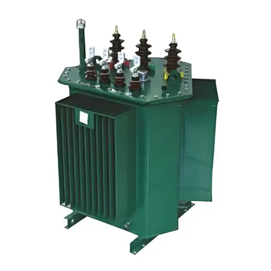
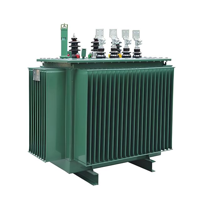
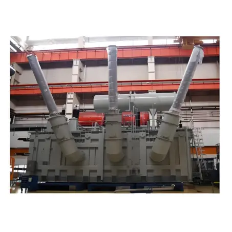
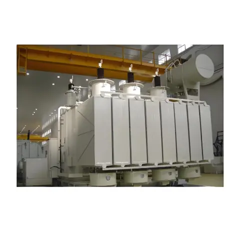
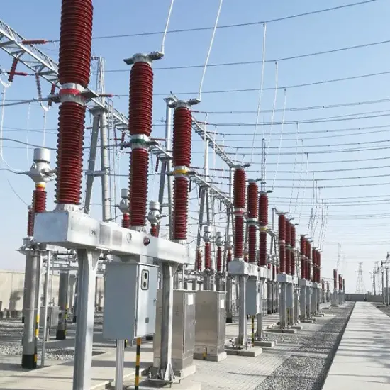
A 161kV 170kV 220kV Transmission Transformer is a key high-voltage power equipment in regional and intercity power grids. It bridges higher-voltage transmission networks (e.g., 500kV) and medium-voltage distribution systems (e.g., 110kV/35kV), stepping down 220kV electricity to lower levels for industrial zones, urban centers, and large-scale infrastructure. Widely deployed in substations and grid interconnection points, it ensures stable power flow over medium-to-long distances (50–200km), supports load balancing, and enhances the reliability of energy distribution across provinces or metropolitan areas.

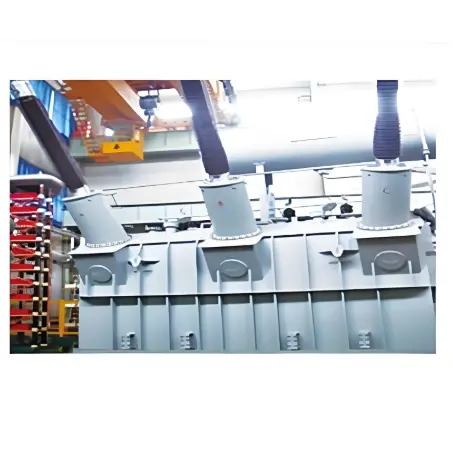
  • 50MVA 220kV Transformer

The voltage classes of some of these Power Transformer include  110kV 115kV 123kV 125kV 126kV 132kV 138kV 145kV 150kV 154kV 161kV 170kV  220kV 225kV 230kV 245kV 275kV 330kV 345kV 363kV 380kV 400kV 500kV Power transformers of voltage ,and aboveand customization is available.

This power transformer is fully compliant with international standards including IEC 60076-1, IEEE C57.12.00, ANSI C57.12.90, AS/NZS 60076.5 and EN 61558-1. It meets quality requirements and is widely adaptable to the operational needs of power grids in multiple overseas regions.

Features of 161kV 170kV 220kV Transmission Transformer

  • Versatile Voltage Matching: Optimized to connect 220kV grids with lower-voltage systems (110kV/35kV), enabling flexible integration into multi-level power networks. This adaptability makes it suitable for both urban and rural transmission scenarios.

  • High Efficiency & Low Loss: Adopts low-loss silicon steel cores and optimized copper windings, reducing no-load and load losses by 15–20% compared to older models. Meets international efficiency standards (e.g., IEC 60076) to minimize energy waste during transmission.

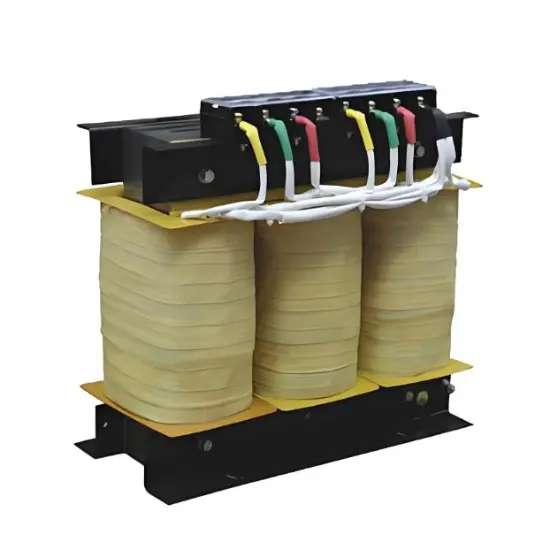
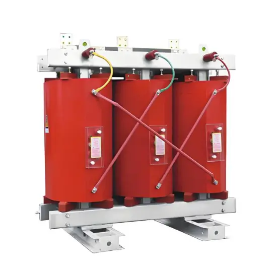
  • Robust Structural Design: Built with sealed oil-immersed tanks or advanced dry-type insulation (for indoor use) to resist moisture, dust, and extreme temperatures (-30°C to 45°C). Corrosion-resistant coatings ensure durability in coastal or industrial environments.

  • Enhanced Safety Mechanisms: Equipped with pressure relief valves, temperature sensors, and gas relay protection to detect faults like short circuits or oil leaks. On-load tap changers (OLTC) allow voltage adjustment under full load, preventing grid instability.

  • Compact & Space-Saving: Designed with reduced footprint for easy installation in urban substations with limited space. Noise-dampening features (e.g., vibration-absorbing bases) comply with environmental regulations in residential areas.

  • Smart Grid Integration: Integrated with IoT-enabled monitoring systems to track real-time parameters (oil quality, winding temperature, load current). Supports remote diagnostics and predictive maintenance, reducing downtime.

  • High Short-Circuit Withstand Capacity: Reinforced windings and rigid core structures withstand transient short-circuit currents, ensuring operational safety during grid faults and extending service life (typically 30+ years).
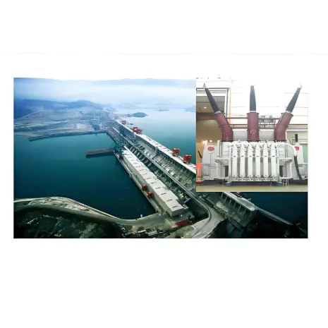
Application Field

  • Power Plant Step-up Substation

  • Industrial Power System

  • Hub Substation

FAQ
Q: What voltage levels are involved in power transformers up to 345kV, and what are the common voltage ratios?
A:
Transformers in this range cover two major power grid levels: High Voltage (HV) and Extra-High Voltage (EHV). The standard voltages and common ratios are as follows:
  • Core voltage levels: High Voltage (HV) includes 33kV, 66kV, 115kV, 132kV, 220kV, and 230kV; Extra-High Voltage (EHV) includes 345kV and 400kV. These are all nominal system voltages specified in international standards.
  • Typical voltage ratios: ① Generator step-up: 345kV/13.8kV; ② Substation step-down: 345kV/34.5kV; ③ Transmission tie-lines (often autotransformers): 345kV/138kV, 345kV/230kV; ④ Other common ratios: 220kV/132kV, 132kV/66kV, 132kV/33kV.
Know your supplier
Online store
On-time delivery rate
Response time
100.0%
≤4h
Company overview
Workplace: 108000m²m² Total staff: 700+ Highest Annual Export(usD): 150000000
Workplace: 108000m²m²
Total staff: 700+
Highest Annual Export(usD): 150000000
Services
Business Type: Design/Manufacture/Sales
Main Categories: High Voltage Electrical Apparatus/Electric transformer
Whole life care manager
Whole-life care management services for equipment procurement, use, maintenance, and after-sales, ensuring safe operation of electrical equipment, continuous control, and worry-free electricity consumption.
The equipment supplier has passed platform qualification certification and technical evaluation, ensuring compliance, professionalism, and reliability from the source.

Related Products

Related Knowledges

  • Impact of DC Bias in Transformers at Renewable Energy Stations Near UHVDC Grounding Electrodes
    Impact of DC Bias in Transformers at Renewable Energy Stations Near UHVDC Grounding ElectrodesWhen the grounding electrode of an Ultra-High-Voltage Direct Current (UHVDC) transmission system is located close to a renewable energy power station, the return current flowing through the earth can cause a rise in ground potential around the electrode area. This ground potential rise leads to a shift in the neutral-point potential of nearby power transformers, inducing DC bias (or DC offset) in their
    01/15/2026
  • HECI GCB for Generators – Fast SF6 Circuit Breaker
    1.Definition and Function1.1 Role of the Generator Circuit BreakerThe Generator Circuit Breaker (GCB) is a controllable disconnect point located between the generator and the step-up transformer, serving as an interface between the generator and the power grid. Its primary functions include isolating generator-side faults and enabling operational control during generator synchronization and grid connection. The operating principle of a GCB is not significantly different from that of a standard c
    01/06/2026
  • Distribution Equipment Transformer Testing, Inspection, and Maintenance
    1.Transformer Maintenance and Inspection Open the low-voltage (LV) circuit breaker of the transformer under maintenance, remove the control power fuse, and hang a “Do Not Close” warning sign on the switch handle. Open the high-voltage (HV) circuit breaker of the transformer under maintenance, close the grounding switch, fully discharge the transformer, lock the HV switchgear, and hang a “Do Not Close” warning sign on the switch handle. For dry-type transformer maintenance: first clean the porcel
    12/25/2025
  • How to Test Insulation Resistance of Distribution Transformers
    In practical work, insulation resistance of distribution transformers is generally measured twice: the insulation resistance between thehigh-voltage (HV) windingand thelow-voltage (LV) winding plus the transformer tank, and the insulation resistance between theLV windingand theHV winding plus the transformer tank.If both measurements yield acceptable values, it indicates that the insulation among the HV winding, LV winding, and transformer tank is qualified. If either measurement fails, pairwise
    12/25/2025
  • Design Principles for Pole-Mounted Distribution Transformers
    Design Principles for Pole-Mounted Distribution Transformers(1) Location and Layout PrinciplesPole-mounted transformer platforms should be located near the load center or close to critical loads, following the principle of “small capacity, multiple locations” to facilitate equipment replacement and maintenance. For residential power supply, three-phase transformers may be installed nearby based on current demand and future growth projections.(2) Capacity Selection for Three-Phase Pole-Mounted Tr
    12/25/2025
  • Transformer Noise Control Solutions for Different Installations
    1.Noise Mitigation for Ground-Level Independent Transformer RoomsMitigation Strategy:First, conduct a power-off inspection and maintenance of the transformer, including replacing aged insulating oil, checking and tightening all fasteners, and cleaning dust from the unit.Second, reinforce the transformer foundation or install vibration isolation devices—such as rubber pads or spring isolators—selected based on the severity of vibration.Finally, strengthen sound insulation at weak points of the ro
    12/25/2025

Related Solutions

  • Intelligent Operation Solution for 12kV Vacuum Circuit Breakers: Integrating Real-time Monitoring & Lifetime Optimization
    Ⅰ. Equipment Operation & MaintenanceIntelligent Monitoring System Integration​Multi-parameter Real-time Monitoring: Embedded sensors (temperature, displacement, Hall effect current sensors) track contact temperature rise, mechanical characteristics (opening/closing speed, overtravel), coil current, and partial discharge signals. Data undergoes preprocessing via edge computing prior to cloud upload.​Lifetime Prediction Model: Dynamically evaluates remaining lifespan using electrical wear data
    06/10/2025
  • SF6 Circuit Breaker Solutions for Outdoor Installation (Anti-Pollution & Seismic Resistance)
    I.Core Challenges in Outdoor Installation​In high-voltage transmission and distribution systems, SF6 circuit breakers are exposed to complex outdoor environments for extended periods, facing the following critical issues:​Pollution & Insulation Degradation​Dust, salt fog, and industrial pollutants in outdoor environments easily adhere to equipment surfaces. In coastal or industrial areas, pollution levels may reach ​Class IV, resulting in insufficient creepage distance and triggering ​flasho
    05/12/2025
  • 12kV Indoor Vacuum Circuit Breaker Southeast Asia Solution: Anti-Corrosion Compact Design
    12kV Indoor Vacuum Circuit Breaker Southeast Asia Solution: Anti-Corrosion Compact DesignⅠ. Executive Summary​Southeast Asia faces rapidly growing electricity demand alongside environmental challenges including high temperatures, humidity, salt spray corrosion, and grid instability. This solution recommends ​Solid Insulated Pole-Mounted Vacuum Circuit Breakers (VCB)​​ featuring ​high reliability, ​compact design, and ​smart monitoring. Tailored for tropical climates and industrial scenarios, it
    06/10/2025
Related Free tools
Haven't found the right supplier yet? Let matching verified suppliers find you. Get Quotation Now
Haven't found the right supplier yet? Let matching verified suppliers find you.
Get Quotation Now
Send inquiry
Download
Get the IEE Business Application
Use the IEE-Business app to find equipment, obtain solutions, connect with experts, and participate in industry collaboration anytime, anywhere—fully supporting the development of your power projects and business.