• Product
  • Suppliers
  • Manufacturers
  • Solutions
  • Free tools
  • Knowledges
  • Experts
  • Communities
Search


DC rod-shaped post porcelain insulator

  • DC rod-shaped post porcelain insulator

Key attributes

Brand Wone Store
Model NO. DC rod-shaped post porcelain insulator
Rated voltage 24kV
Rated frequency 50/60Hz
Series ZCW

Product descriptions from the supplier

Description

Product Description

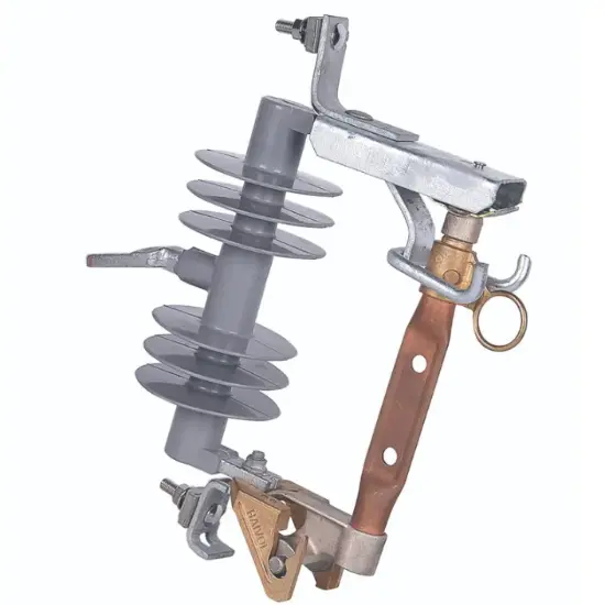
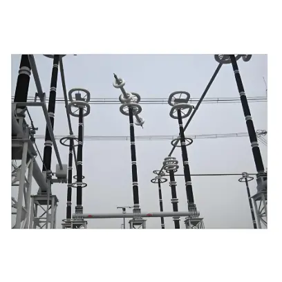
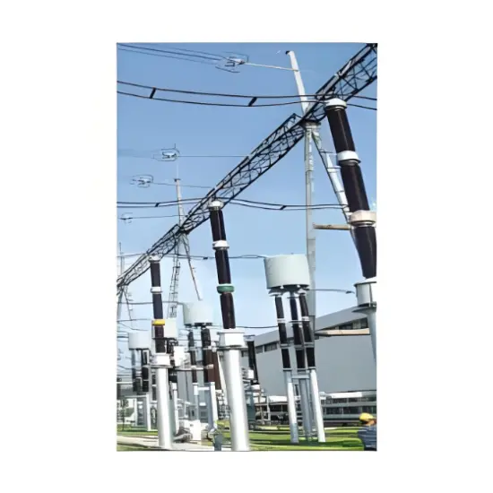
DC rod-shaped post porcelain insulators are specialized components designed for direct current (DC) power systems, serving as critical elements that provide both mechanical support and electrical insulation. They are primarily used to secure and insulate conductors, busbars, or other live parts in DC substations, transmission lines, and industrial DC equipment, preventing current leakage to grounded structures and ensuring stable, safe operation of high-voltage DC networks.

Main Features

  • DC-Specific Insulation Performance: Optimized for direct current environments, with enhanced resistance to polarization and electrochemical corrosion, ensuring reliable insulation under steady DC voltage.

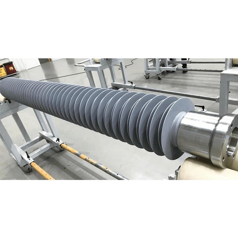
  • Robust Structural Support: The rod-shaped post design offers strong mechanical stability, capable of withstanding conductor tension, vibration, and external loads to keep components securely positioned.

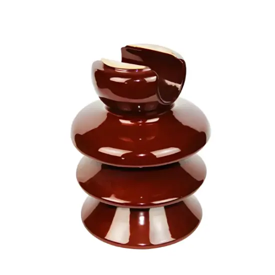
  • High-Quality Porcelain Construction: Made from dense, high-purity porcelain material, providing excellent dielectric strength and resistance to electrical breakdown even in harsh conditions.

  • Environmental Durability: Resistant to extreme temperatures, humidity, UV radiation, and industrial pollution, maintaining performance in both indoor and outdoor DC power applications.

  • Compatibility with DC Systems: Engineered to integrate seamlessly with DC transmission and distribution setups, supporting the specific voltage and current requirements of DC networks.

Main Parameters

Model

Rated voltage

The damage load is not small

Creepage distance

Main Dimensions (mm)

weight


curved

torsion


Overall height

Maximum umbrella diameter

Upper mounting holes

lower mounting holes


kV

kN

kN.m

mm

H

D

D1-n-d1

D2-n-d2

kg

ZSW±20kV/8kN

±24

8


4615

1700

305

275-8-Φ18

275-8-Φ18

182

ZSW±50kV/12.5kN

±52

12.5

10

5730

1900

375

300-8-Φ18

300-8-Φ18

255

ZSW±50kV/40kN

±52

40

20

4250

1700

410

356-8-Φ18

356-8-Φ18

325

ZSW±90kV/10kN

±95

10


5130

2200

410

325-8-Φ18

325-8-Φ18

373

ZSW±90kV/48kN

±95

48

15

5130

2200

460

375-12-Φ22

375-12-Φ22

527

ZSW±120kV/8kN

±124

8


6696

3800

380

300-8-Φ18

325-8-Φ18

526

ZSW±300kV/8kN

±310

8


4340

4400

310

300-8-Φ18

325-8-Φ18

587

ZSW±400kV/8kN

±408

8


5712

5700

340

300-8-Φ18

356-8-Φ18

824

ZSW±400kV/10kN

±408

10

10

22032

7615

435

300-8-Φ18

375-12-Φ22

1273

ZSW±400kV/12.5kN

±412

12.5

10

25132

7615

452

300-8-Φ18

375-12-Φ22

1520

ZSW±400kV/12.5kN

±412

12.5

10

14956

7615

450

300-8-Φ18

375-12-Φ22

1410

ZSW±500kV/10kN

±500

10

10

24790

8000

420

270-4-Φ18

325-8-Φ18

1234

ZSW±500kV/10kN

±500

10

10

27800

8000

420

250-4-Φ18

325-8-Φ18

1198

ZSW±500kV/16kN

±500

16

10

23700

8000

480

270-4-Φ18

410-8-Φ22


ZSW±500kV/16kN

±500

16

10

26700

8000

480

250-4-Φ18

410-8-Φ22


ZSW±500kV/16kN

±515

16

10

28110

9200

485

325-8-Φ18

450-12-Φ22

2170

ZSW±600kV/8kN

±610

8


8540

5900

340

300-8-Φ18

356-8-Φ18

854

ZSW±600kV/8kN

±614

8


8596

6905

365

300-8-Φ18

375-12-Φ22

1126

ZSW±660kV/12.5kN

±680

12.5


17425

7480

365

300-8-Φ18

375-12-Φ22

1241

ZSW±700kV/8kN

±716

8


10024

7500

365

300-8-Φ18

375-12-Φ22

1217

ZSW±800kV/10kN

±800

10

20

38400

13200

490

450-12-Φ22

450-12-Φ22

4008

ZSW±800kV/10kN

±800

10

20

34460

13200

490

450-12-Φ22

450-12-Φ22

4090

ZSW±800kV/10kN

±816

10

10

40050

10970

472

300-8-Φ18

400-12-Φ22

2360

ZSW±800kV/10kN

±816

10

20

39180

10980

472

400-12-Φ22

400-12-Φ22

3090

ZSW±800kV/12.5kN

±816

12.5

20

32000

11000

490

450-12-Φ22

450-12-Φ22

3285

ZSW±800kV/12.5kN

±816

12.5

20

34460

11000

490

450-12-Φ22

450-12-Φ22

3355

ZSW±800kV/12.5kN

±816

12.5

20

39171

12000

492

450-12-Φ22

450-12-Φ22

3956

ZSW±1000kV/8kN

±1020

8

10

51000

14000

475

300-8-Φ18

465-16-Φ22

3150

Know your supplier
Online store
On-time delivery rate
Response time
100.0%
≤4h
Company overview
Workplace: 1000m² Total staff: Highest Annual Export(usD): 300000000
Workplace: 1000m²
Total staff:
Highest Annual Export(usD): 300000000
Services
Business Type: Sales
Main Categories: Wire cable/High Voltage Electrical Apparatus/Low Voltage Electrical Apparatus/Instrument meters/New energy/Tester/Integrated Electrical Equipment/Production equipment/Generator/Electrical fittings/Instrument Transformer/Equipment Parts
Whole life care manager
Whole-life care management services for equipment procurement, use, maintenance, and after-sales, ensuring safe operation of electrical equipment, continuous control, and worry-free electricity consumption.
The equipment supplier has passed platform qualification certification and technical evaluation, ensuring compliance, professionalism, and reliability from the source.

Related Products

Related Knowledges

  • Faults and Handling of Single-phase Grounding in 10kV Distribution Lines
    Characteristics and Detection Devices for Single-Phase Ground Faults1. Characteristics of Single-Phase Ground FaultsCentral Alarm Signals:The warning bell rings, and the indicator lamp labeled “Ground Fault on [X] kV Bus Section [Y]” illuminates. In systems with a Petersen coil (arc suppression coil) grounding the neutral point, the “Petersen Coil Operated” indicator also lights up.Insulation Monitoring Voltmeter Indications:The voltage of the faulted phase decreases (in
    01/30/2026
  • Neutral point grounding operation mode for 110kV~220kV power grid transformers
    The arrangement of neutral point grounding operation modes for 110kV~220kV power grid transformers shall meet the insulation withstand requirements of transformer neutral points, and shall also strive to keep the zero-sequence impedance of substations basically unchanged, while ensuring that the zero-sequence comprehensive impedance at any short-circuit point in the system does not exceed three times the positive-sequence comprehensive impedance.For 220kV and 110kV transformers in new constructi
    01/29/2026
  • Why Do Substations Use Stones, Gravel, Pebbles, and Crushed Rock?
    Why Do Substations Use Stones, Gravel, Pebbles, and Crushed Rock?In substations, equipment such as power and distribution transformers, transmission lines, voltage transformers, current transformers, and disconnect switches all require grounding. Beyond grounding, we will now explore in depth why gravel and crushed stone are commonly used in substations. Though they appear ordinary, these stones play a critical safety and functional role.In substation grounding design—especially when multiple gr
    01/29/2026
  • Why Must a Transformer Core Be Grounded at Only One Point? Isn't Multi-Point Grounding More Reliable?
    Why Does the Transformer Core Need to Be Grounded?During operation, the transformer core, along with the metal structures, parts, and components that fix the core and windings, are all situated in a strong electric field. Under the influence of this electric field, they acquire a relatively high potential with respect to ground. If the core is not grounded, a potential difference will exist between the core and the grounded clamping structures and tank, which may lead to intermittent discharge.I
    01/29/2026
  • Understanding Transformer Neutral Grounding
    I. What is a Neutral Point?In transformers and generators, the neutral point is a specific point in the winding where the absolute voltage between this point and each external terminal is equal. In the diagram below, pointOrepresents the neutral point.II. Why Does the Neutral Point Need Grounding?The electrical connection method between the neutral point and earth in a three-phase AC power system is called theneutral grounding method. This grounding method directly affects:The safety, reliabilit
    01/29/2026
  • What’s the Difference Between Rectifier Transformers and Power Transformers?
    What is a Rectifier Transformer?"Power conversion" is a general term encompassing rectification, inversion, and frequency conversion, with rectification being the most widely used among them. Rectifier equipment converts input AC power into DC output through rectification and filtering. A rectifier transformer serves as the power supply transformer for such rectifier equipment. In industrial applications, most DC power supplies are obtained by combining a rectifier transformer with rectifier equ
    01/29/2026

Related Solutions

  • Dedicated Vacuum Contactor Solution for Port Shore Power Systems
    I. Background and Challenges​Shore power systems have become core technical equipment for ports to reduce carbon emissions and noise pollution. However, these systems face two major challenges in the harsh operational environment of ports:​Severe Environmental Corrosion: High humidity and salt spray in port areas cause serious corrosion to metal components and enclosures of electrical equipment, significantly impacting electrical lifespan and operational reliability.​High Switching Requirements:
    09/13/2025
  • ABB Vacuum Contactor KC2 Power Supply System Technical Transformation Plan
    Issue Overview​The 10kV air compressor starting system of a company utilizes the ABB vacuum contactor KC2 as the control component for the operating circuit. The dedicated wide-voltage power supply module paired with this contactor presents the following issues:​Frequent failures: The power supply module fails to properly transition the voltage from 300V to 12V, resulting in fuse blowouts.​Poor heat dissipation: Enclosed installation of the module leads to insufficient heat dissipation, acceler
    09/13/2025
  • Solution for Medium-Voltage Motor Control and Protection Using Vacuum Contactor-Fuse (VCF) in a Coal Conveying System
    1.Project BackgroundA coal conveying system comprises 15 belt conveyors driven by medium-voltage motors. The system operates under complex conditions, with motors often subjected to heavy loads and frequent starts. To address these challenges and achieve effective control and reliable protection during motor startup, the project comprehensively adopts Vacuum Contactor-Fuse (VCF) combination devices for the 6kV medium-voltage motor power distribution. This solution details the technical features,
    09/13/2025
Haven't found the right supplier yet? Let matching verified suppliers find you. Get Quotation Now
Haven't found the right supplier yet? Let matching verified suppliers find you.
Get Quotation Now
Send inquiry
+86
Click to upload file
Download
Get the IEE Business Application
Use the IEE-Business app to find equipment, obtain solutions, connect with experts, and participate in industry collaboration anytime, anywhere—fully supporting the development of your power projects and business.