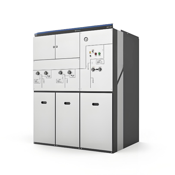
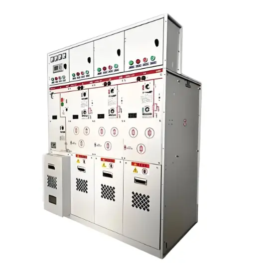
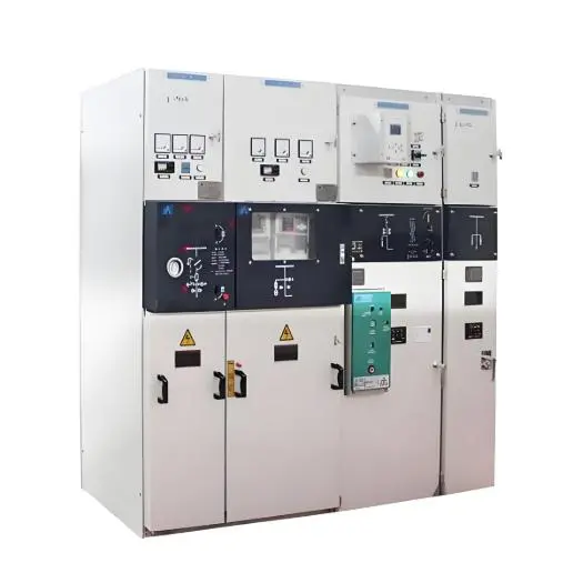
Fully air insulated switchgear of 12kV/24kV
Key attributes
| Brand | ROCKWILL |
| Model NO. | Fully air insulated switchgear of 12kV/24kV |
| Rated voltage | 24kV |
| Rated normal current | 630A |
| Rated frequency | 50/60Hz |
| Rated short circuit breaking current | 16kA |
| Series | Eok |
Product descriptions from the supplier
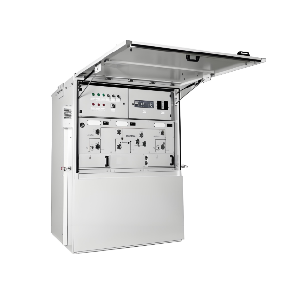
Product overview
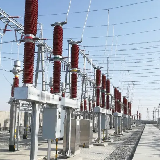
As the power industry evolves, the miniaturization of electrical equipment represents a key future trend and an urgent need for current power consumers. Miniaturized electrical equipment not only saves land and civil engineering costs but also reduces the use of greenhouse gases like sulfur hexafluoride (SF6), thereby meeting ecological and environmental protection requirements. Leveraging years of extensive experience in high-voltage electrical design and incorporating globally advanced technical design philosophies, our company has developed the latest The EoK-12/24 Fully air insulated switchgear This product is tailored for power utilities and enterprises pursuing high power supply reliability, advancing distribution automation upgrades, and operating in harsh environments. It serves not just as a simple line switch but as a critical component in building smart, resilient distribution grids.
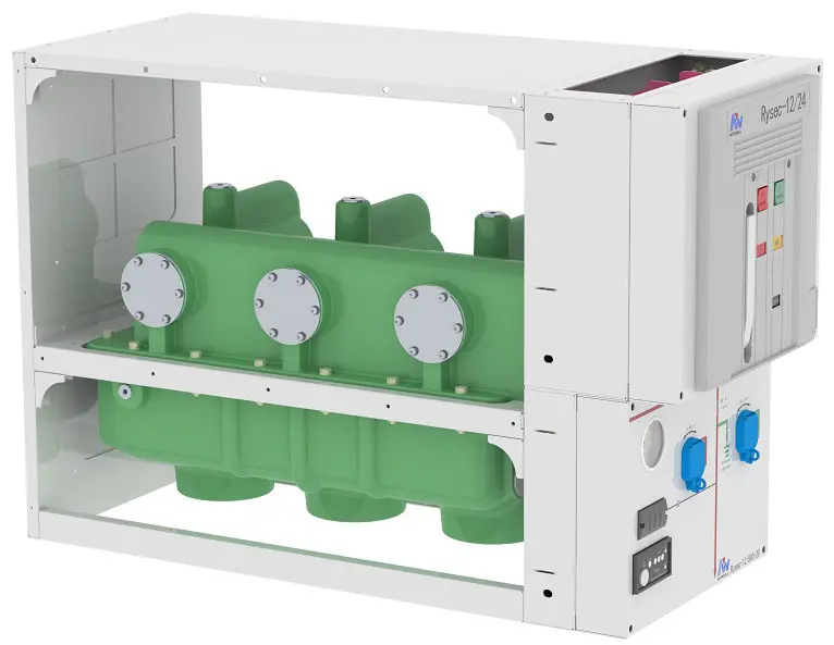
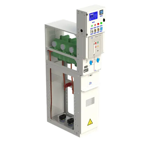
Product Structure Analysis
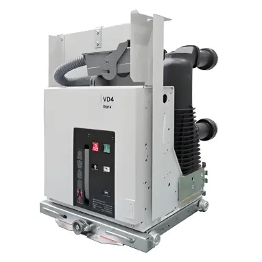
The product structure of ROCKWELL RySec Compact physically embodies its integrated multi-function concept. Its design is sophisticated and clearly layered, primarily consisting of three core components: the upper circuit breaker module, the lower isolation/earthing switch module, and the integrated operating and interlocking mechanism.
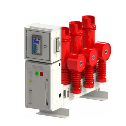
Upper Structure: Circuit Breaker Module
Core Function: Undertakes the tasks of closing the circuit, carrying the load current, and interrupting fault currents.
Casing Material: Fabricated using epoxy resin casting, which provides outstanding electrical insulation strength and mechanical strength.
Arc Interruption Unit: Encapsulated within the casing are three vacuum interrupter chambers, the core interrupting components of the circuit breaker. These chambers efficiently and cleanly extinguish the arc at current zero-crossing points.
Insulating Medium: The chamber is filled with Pure air/N2 gas as the insulating medium, ensuring high insulation performance within a compact design.
Lower Structure: Isolation and Earthing Switch Module
Core Function: Provides physical isolation of the circuit (disconnector) and safe earthing of cables (earthing switch).
Structural Material: Crafted from epoxy resin casting, delivering exceptional electrical insulation strength and mechanical robustness.
Integrated Component: The lower housing incorporates a capacitive bushing, enabling connection to voltage indication equipment without the need for an additional, separate capacitive voltage divider within the switchgear.
Operating and Interlocking Mechanism
The RySec is equipped with two independent yet mechanically interlocked operating mechanisms, ensuring logical and safe operation sequences.
Circuit Breaker Operating Mechanism (EL Series)
1) Type: Spring-operated, trip-free mechanism.
2) Features:
a) Enables local (manual) or remote (electric) control via closing/opening coils and a motor.
b) Includes mechanical anti-pumping function to prevent repeated closing/latching under fault conditions.
c) Springs are charged during the closing operation, storing energy for rapid contact separation during tripping.
d) The mechanism is mechanically latched in the closed position and released by a separate trip signal, ensuring instantaneous opening independent of operator intervention.
Disconnector/Earthing Switch Operating Mechanism (1S Series)
1) Type: Double-spring operating mechanism.
2) Features:
a) Provides two independent operating interfaces for disconnector and earthed switch operations, respectively.
b) The operating force
Core Safety Structure: Mechanical Interlocking System
The most critical safety feature of the product structure is its built-in, non-bypassable mechanical interlocking system
1) Circuit Breaker-Disconnector Interlock
Prevents operation of the disconnector when the circuit breaker is in the closed position, avoiding load-breaking or making operations on the disconnector
2) Disconnector-Earthing Switch Interlock
Implemented via independent operating lever seats, ensuring:
a) The earthing switch can only be closed after the disconnector is fully open.
b) The disconnector can only be closed after the earthing switch is open
3) Cabinet Door Interlock
Mechanically linked to the switchgear door, ensuring:
a) The cable compartment door can be opened only when the disconnector is open and the earthing switch is closed (safely grounding the cable side).
b) When the door is open, the earthing switch is mechanically blocked from opening
Technical Parameters
Parameter Name |
Value |
|
Rated voltage |
12KV |
24KV |
Insulation voltage |
12KV |
24KV |
Power frequency withstand voltage (50/60 Hz, 1 min) |
28KV |
50KV |
Lightning impulse withstand voltage (BIL 1.2/50 us) |
75KV |
125KV |
Rated frequency |
50/60Hz |
50/60Hz |
Rated current |
630A |
630A |
Short-time withstand current (3s) |
12.5/16/21KA |
12.5/16/21KA |
Performance of breaking part (lEC 62271-100) |
||
Breaking capacity |
- |
|
Short-circuit current |
12.5/16/21KA |
|
No-load transformers |
6.3A |
|
No-load lines. |
10A |
|
No-load cables |
16A |
|
Capacitive currents |
400A |
|
Making capacity |
32.5/41.5/45.5kAp |
|
Operating sequence |
O-0.3s-CO-15s-CO |
|
Opening time |
40~55ms |
|
Arcing time |
10~15ms |
|
Total break-time |
50~70ms |
|
Closing time |
40~55ms |
|
Electrical life |
E2 |
|
Mechanical life |
M2. 10000 mechanical operations |
|
Capacitive current breaking class |
C2 |
|
Line disconnector performance (IEC 62271-102) |
||
Electrical life |
E0 |
|
Mechanical life |
M0- 1.000 mechanical operations |
|
Earthing switch performance (IEC 62271-102) |
||
Electrical life |
E2 |
|
Mechanical life |
M0- 1.000 mechanical operations |
|
Earthing switch making capacity |
32.5/41.5/54.5kAp |
|
Other characteristics |
||
Center-distance between phases |
230mm |
|
Operating temperature |
-15℃&~+40℃ |
|
Maximum installation altitude |
3000masl |
|
External Dimensions |
Length |
|
Width |
||
Height |
||
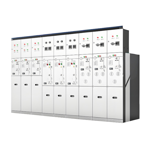
Application Scenarios
The RySec Compact is an ideal choice for secondary distribution applications, particularly suited for:
Medium-sized distribution substations.
Protection of overhead lines or cables.
Switching of capacitor banks.
Motor protection.

Core electrical indicators: rated voltage of 12KV/24KV, rated current of 630A, short-time withstand current of 12.5/16/21KA, short-circuit current breaking capacity of 12.5/16/21KA, capacitor current breaking capacity of 400A; core mechanical indicators: circuit breaker mechanical life of 10000 times, opening/closing time of 40-55ms, total breaking time of 50-70ms. Impact effect:
- Rated voltage/current determines the level of medium voltage distribution system adapted to the equipment;
- The short-circuit withstand/break capacity is directly related to the arc extinguishing efficiency and safety protection capability of the equipment in the event of a fault;
- The mechanical lifespan and operating time affect the long-term stable operation duration and fault response speed of the equipment, ensuring the continuity of power supply.
The main applicable scenarios include medium-sized distribution stations, overhead line/cable protection, capacitor bank switching, and motor protection. Key limitations of installation environment:
- Temperature: The normal operating temperature range is -15 ℃ to+40 ℃. If you need to serve in an environment of -25 ℃ or store in an environment of -40 ℃, you need to contact the manufacturer in advance for customization;
- Altitude: The maximum installation altitude for conventional equipment is 1000m. For high-altitude areas exceeding this altitude, the manufacturer should be informed at the time of ordering and insulation reinforcement measures should be taken;
- Humidity: Suitable for high humidity environments with a daily average humidity of 100%, without the need for additional protection.
Answer: The core competitive advantages are concentrated in the four dimensions of "integration, safety, environmental protection, and efficiency":
- Compact integration, three in one design+environmentally friendly insulation medium, with a width of only 420mm, significantly saving space and infrastructure/material costs;
- Safety redundancy, built-in unavoidable mechanical interlocking system, eliminating misoperation from the root, circuit breaker with a mechanical lifespan of 10000 times and a sealing guarantee of more than 30 years for the shell, and reliability verification through full type testing;
- Green and environmentally friendly, using pure air/N ₂ to replace SF ₆ greenhouse gases, achieving zero carbon emissions and zero waste, in line with global environmental trends;
- The low TCO advantage reduces on-site assembly processes, supports plug and play accessories and quick customization, and lowers installation, maintenance, and long-term usage costs.

Related Products
-
RMR Series Gas-Insulated Metal-enclosed Switchgear

-
12/24kV SF6 GIS for Secondary Distribution/Ring Main Unit
-
17.5kV SF6 GIS for Secondary Distribution / Ring Main Unit
-
40.5kV series SF6 gas-insulated switchgear
-
11kV SF6 MV Ring Main Unit Switchgear

-
10.5kV 11kV 11.5kV 12kV Solid Insulated Ring Main Unit/Switchgear source manufacturer
-
13.2kV 12kV 14.5kV 15kV 21.9kV Solid insulation switchgear/Ring Main Unit direct supply
Related Knowledges
-
 Main Transformer Accidents and Light Gas Operation Issues1. Accident Record (March 19, 2019)At 16:13 on March 19, 2019, the monitoring background reported a light gas action of No. 3 main transformer. In accordance with the Code for Operation of Power Transformers (DL/T572-2010), operation and maintenance (O&M) personnel inspected the on-site condition of No. 3 main transformer.On-site confirmation: The WBH non-electrical protection panel of No. 3 main transformer reported a Phase B light gas action of the transformer body, and the reset was ineff02/05/2026
 -
 Faults and Handling of Single-phase Grounding in 10kV Distribution LinesCharacteristics and Detection Devices for Single-Phase Ground Faults1. Characteristics of Single-Phase Ground FaultsCentral Alarm Signals:The warning bell rings, and the indicator lamp labeled “Ground Fault on [X] kV Bus Section [Y]” illuminates. In systems with a Petersen coil (arc suppression coil) grounding the neutral point, the “Petersen Coil Operated” indicator also lights up.Insulation Monitoring Voltmeter Indications:The voltage of the faulted phase decreases (in01/30/2026
 -
 Neutral point grounding operation mode for 110kV~220kV power grid transformersThe arrangement of neutral point grounding operation modes for 110kV~220kV power grid transformers shall meet the insulation withstand requirements of transformer neutral points, and shall also strive to keep the zero-sequence impedance of substations basically unchanged, while ensuring that the zero-sequence comprehensive impedance at any short-circuit point in the system does not exceed three times the positive-sequence comprehensive impedance.For 220kV and 110kV transformers in new constructi01/29/2026
 -
 Why Do Substations Use Stones, Gravel, Pebbles, and Crushed Rock?Why Do Substations Use Stones, Gravel, Pebbles, and Crushed Rock?In substations, equipment such as power and distribution transformers, transmission lines, voltage transformers, current transformers, and disconnect switches all require grounding. Beyond grounding, we will now explore in depth why gravel and crushed stone are commonly used in substations. Though they appear ordinary, these stones play a critical safety and functional role.In substation grounding design—especially when multiple gr01/29/2026
 -
 Why Must a Transformer Core Be Grounded at Only One Point? Isn't Multi-Point Grounding More Reliable?Why Does the Transformer Core Need to Be Grounded?During operation, the transformer core, along with the metal structures, parts, and components that fix the core and windings, are all situated in a strong electric field. Under the influence of this electric field, they acquire a relatively high potential with respect to ground. If the core is not grounded, a potential difference will exist between the core and the grounded clamping structures and tank, which may lead to intermittent discharge.I01/29/2026
 -
 Understanding Transformer Neutral GroundingI. What is a Neutral Point?In transformers and generators, the neutral point is a specific point in the winding where the absolute voltage between this point and each external terminal is equal. In the diagram below, pointOrepresents the neutral point.II. Why Does the Neutral Point Need Grounding?The electrical connection method between the neutral point and earth in a three-phase AC power system is called theneutral grounding method. This grounding method directly affects:The safety, reliabilit01/29/2026
Related Solutions
-
 Intelligent Operation Solution for 12kV Vacuum Circuit Breakers: Integrating Real-time Monitoring & Lifetime OptimizationⅠ. Equipment Operation & MaintenanceIntelligent Monitoring System IntegrationMulti-parameter Real-time Monitoring: Embedded sensors (temperature, displacement, Hall effect current sensors) track contact temperature rise, mechanical characteristics (opening/closing speed, overtravel), coil current, and partial discharge signals. Data undergoes preprocessing via edge computing prior to cloud upload.Lifetime Prediction Model: Dynamically evaluates remaining lifespan using electrical wear data06/10/2025
 -
 SF6 Circuit Breaker Solutions for Outdoor Installation (Anti-Pollution & Seismic Resistance)I.Core Challenges in Outdoor InstallationIn high-voltage transmission and distribution systems, SF6 circuit breakers are exposed to complex outdoor environments for extended periods, facing the following critical issues:Pollution & Insulation DegradationDust, salt fog, and industrial pollutants in outdoor environments easily adhere to equipment surfaces. In coastal or industrial areas, pollution levels may reach Class IV, resulting in insufficient creepage distance and triggering flasho05/12/2025
 -
 12kV Indoor Vacuum Circuit Breaker Southeast Asia Solution: Anti-Corrosion Compact Design12kV Indoor Vacuum Circuit Breaker Southeast Asia Solution: Anti-Corrosion Compact DesignⅠ. Executive SummarySoutheast Asia faces rapidly growing electricity demand alongside environmental challenges including high temperatures, humidity, salt spray corrosion, and grid instability. This solution recommends Solid Insulated Pole-Mounted Vacuum Circuit Breakers (VCB) featuring high reliability, compact design, and smart monitoring. Tailored for tropical climates and industrial scenarios, it06/10/2025


