| Brand | Vziman |
| Model NO. | Single-phase pad-mounted transformers with protective functions |
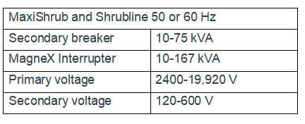
| Rated frequency | 50/60Hz |
| Primary voltage | 2400-19920 V |
| Secondary voltage | 120-600 V |
| Capacity range | 10-167 kVA |
| Series | ZSG |
Descripton:
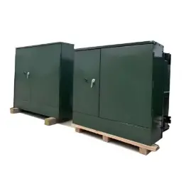
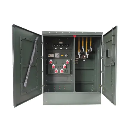
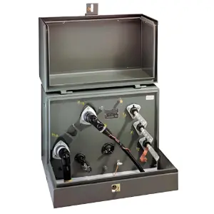
The Completely Self-Protection (CSP) single-phase pad-mounted transformer is designed with the core objective of achieving excellent performance. It integrates a directly connected primary surge arrester, a MagneX arc extinguishing chamber, or a secondary circuit breaker with a built-in primary voltage fuse. There is no need to install additional independent protective equipment, which significantly reduces the installation cost.
The power range of this series of transformers covers 10 - 75 kVA. When equipped with a MagneX arc extinguishing chamber, the power range can be expanded to 10 - 167 kVA, and its performance fully meets or even exceeds relevant standards such as ANSI and NEMA.
In addition, the CSP transformer supports two types of filling media. It can be filled with standard electrical-grade mineral insulating oil or FR3 liquid with excellent fire resistance, flexibly adapting to different usage scenarios.
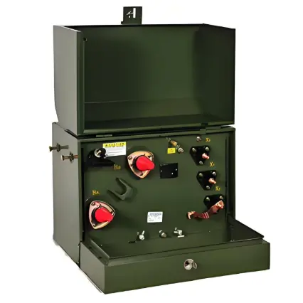
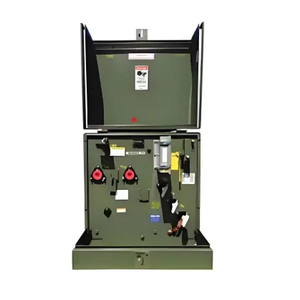
Equipped with an internal overcurrent device and a surge arrester, it can achieve efficient overvoltage protection without the need for external independent protective components. For secondary faults and overloads, it can provide dual reliable protection through a secondary circuit breaker with weak links or an optional MagneX arc extinguishing chamber.
It supports the free choice of two filling media: FR3 fireproof insulating oil, which greatly enhances the fire safety level; or standard electrical-grade mineral oil to meet regular usage requirements. The product performance comprehensively surpasses industry standards and performs excellently in terms of ANSI specifications, NEMA standards, and DOE energy efficiency requirements.
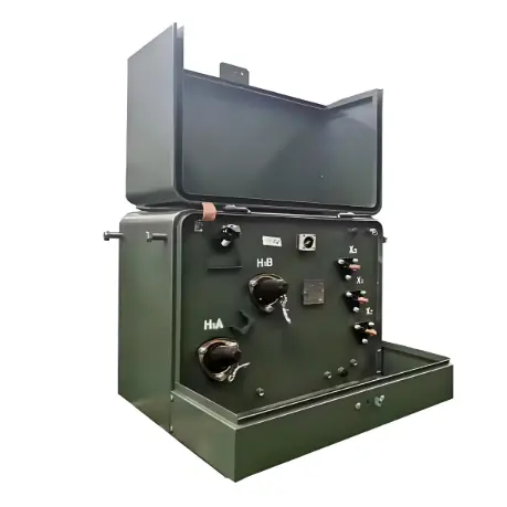
The core and coils are deeply optimized in design. Aiming to achieve high reliability and a low failure rate, it offers two materials, grain-oriented steel and amorphous steel, to adapt to different performance needs. Both the high-voltage and low-voltage bushing terminals are tinned, making them compatible with aluminum and copper conductors to ensure stable and reliable electrical connections.
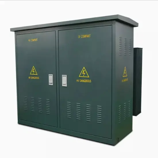
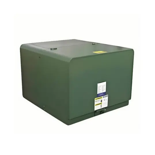
The exterior design takes into account both functionality and aesthetics, offering two style options: the MaxiShrub style equipped with an ANSI Type-1 front panel, or the Shrubline style with an ANSI Type-2 front panel. Both adopt a low-profile design and can better blend into the surrounding environment.
Technical Parameters:
Meet or exceeds ANSI, NEMA and DOE2016 standards
IEEE standards C57.12.00, C57.12.38, C57.12.28, C57.12.35, C57.12.90, C57. 91 and C57.154
NEMA standards, NEMA TR 1 (R2000)
Department of Energy Efficiency Standard, 10 CFR Part 431
Tank coating exceeds IEEE Std C57.12.28-2005 and C57.12.29-2005 standards (stainless steel units only)
Full compliance with IEEE Std C57.12.28-2005 standard enclosure integrity requirements
FR3 fluid or electrical grade mineral oil
Cores and coils designed for high reliability and low field failure rates: Available in grain-oriented electrical or amorphous steel
The transformer shall be designed in accordance with this specification and shall have an Average Winding Rise (AWR) of one of the following:
55 °C, 55/65 °C, 65 °C
The applicable AWR rating shall be specified on the inquiry
The transformer shall be designed in accordance with this specification and shall have one of the following kVA ratings:
10, 15, 25, 37.5, 50, 75, 100, 167
The applicable kVA rating shall be specified on the inquiry
Quality System ISO 9001 certified