• Product
  • Suppliers
  • Manufacturers
  • Solutions
  • Free tools
  • Knowledges
  • Experts
  • Communities
Search


UHF Partial Discharge Detector

  • UHF Partial Discharge Detector

Key attributes

Brand Rw Energy
Model NO. UHF Partial Discharge Detector
Rated frequency 50/60Hz
Series APD100

Product descriptions from the supplier

Description

General

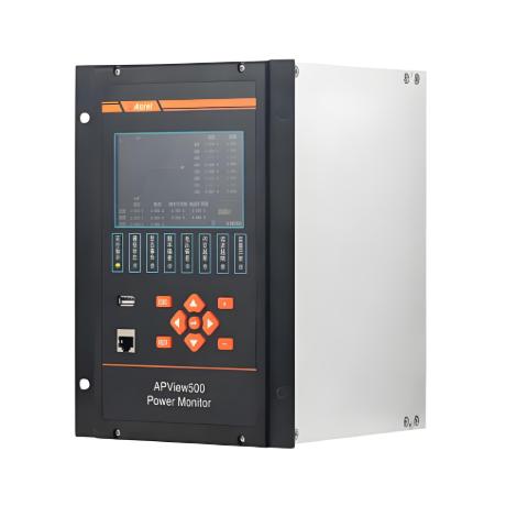
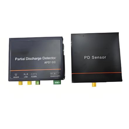
The APD series high-voltage switchgear partial discharge monitoring device detects the electromagnetic wave radiation generated along with partial discharge and automatically determines the actual detection frequency of on-site partial discharge. Then, data such as the number and frequency of partial discharge detected are uploaded to the server.

Feature

  • Power supply: DC10~30V, ≤3W; Standard 220V adapter;

  • Measuring range: -60dBm~+10dBm;

  • Measurement content: discharge amplitude, discharge frequency;

  • Connecting cable: coaxial cable;

  • Communication mode: 1 RS485, MODBUS-RTU protocol; 1 way Lora wireless communication;

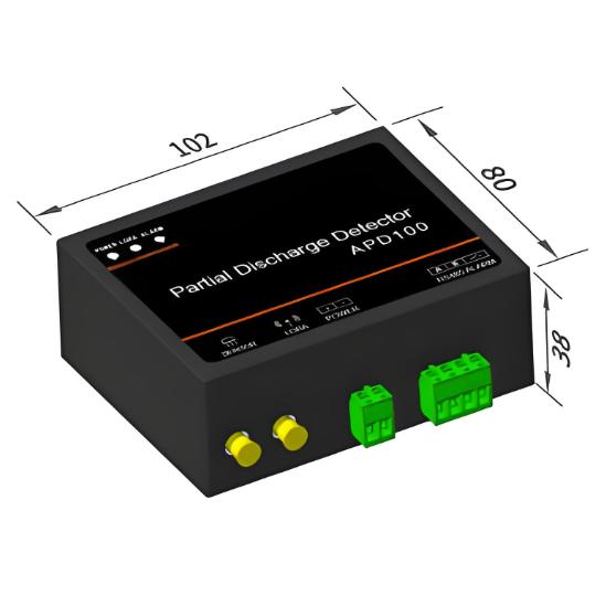
  • Installation method: guide rail installation.

Technical Parameter

Item Features

Transceiver

ATC450-C


Power Source DC24V

Power Consumption


≤1W

points


≤60

Resolution


0.1℃

Communication


RS485

Protocol


MODBUS-RTU

Baud rate (bps)


2400、4800、9600、19200

Environment


Temperature:-20 ℃~+55 ℃;Humidity:≤95%

Dimension

FAQ for
Q: What devices can be monitored?
A:

Specially designed for 10kV~35kV switchgear, transformers, and cable terminals. Timely treatment of partial discharge is necessary to extend equipment lifespan and avoid major repairs. Specially suitable for use in substations and factory distribution rooms, serving as a sentinel for power safety.

Q: Is the installation complicated?
A:

Super simple! Install the guide rail and connect the coaxial cable. Supports RS485 and Lora wireless communication, with data directly transmitted to the monitoring system. Debugging can be done in a few minutes without the need for a professional electrician, even small businesses can install it themselves.

Q: Is partial discharge detection accurate?
A:

UHF technology accurately captures the discharge electromagnetic waves inside the switchgear, with an accuracy of -60dBm to+10dBm. Automatic identification of discharge type and location is more accurate than traditional methods, providing early warning of equipment hazards, avoiding unexpected power outages, and ensuring factory safety.

Know your supplier
Online store
On-time delivery rate
Response time
100.0%
≤4h
Company overview
Workplace: 30000m² Total staff: Highest Annual Export(usD): 100000000
Workplace: 30000m²
Total staff:
Highest Annual Export(usD): 100000000
Services
Business Type: Design/Manufacture/Sales
Main Categories: High Voltage Electrical Apparatus/Low Voltage Electrical Apparatus/Instrument meters/New energy/Tester/Robot
Whole life care manager
Whole-life care management services for equipment procurement, use, maintenance, and after-sales, ensuring safe operation of electrical equipment, continuous control, and worry-free electricity consumption.
The equipment supplier has passed platform qualification certification and technical evaluation, ensuring compliance, professionalism, and reliability from the source.

Related Products

Related Knowledges

  • Main Transformer Accidents and Light Gas Operation Issues
    1. Accident Record (March 19, 2019)At 16:13 on March 19, 2019, the monitoring background reported a light gas action of No. 3 main transformer. In accordance with the Code for Operation of Power Transformers (DL/T572-2010), operation and maintenance (O&M) personnel inspected the on-site condition of No. 3 main transformer.On-site confirmation: The WBH non-electrical protection panel of No. 3 main transformer reported a Phase B light gas action of the transformer body, and the reset was ineff
    02/05/2026
  • Faults and Handling of Single-phase Grounding in 10kV Distribution Lines
    Characteristics and Detection Devices for Single-Phase Ground Faults1. Characteristics of Single-Phase Ground FaultsCentral Alarm Signals:The warning bell rings, and the indicator lamp labeled “Ground Fault on [X] kV Bus Section [Y]” illuminates. In systems with a Petersen coil (arc suppression coil) grounding the neutral point, the “Petersen Coil Operated” indicator also lights up.Insulation Monitoring Voltmeter Indications:The voltage of the faulted phase decreases (in
    01/30/2026
  • Neutral point grounding operation mode for 110kV~220kV power grid transformers
    The arrangement of neutral point grounding operation modes for 110kV~220kV power grid transformers shall meet the insulation withstand requirements of transformer neutral points, and shall also strive to keep the zero-sequence impedance of substations basically unchanged, while ensuring that the zero-sequence comprehensive impedance at any short-circuit point in the system does not exceed three times the positive-sequence comprehensive impedance.For 220kV and 110kV transformers in new constructi
    01/29/2026
  • Why Do Substations Use Stones, Gravel, Pebbles, and Crushed Rock?
    Why Do Substations Use Stones, Gravel, Pebbles, and Crushed Rock?In substations, equipment such as power and distribution transformers, transmission lines, voltage transformers, current transformers, and disconnect switches all require grounding. Beyond grounding, we will now explore in depth why gravel and crushed stone are commonly used in substations. Though they appear ordinary, these stones play a critical safety and functional role.In substation grounding design—especially when multiple gr
    01/29/2026
  • Why Must a Transformer Core Be Grounded at Only One Point? Isn't Multi-Point Grounding More Reliable?
    Why Does the Transformer Core Need to Be Grounded?During operation, the transformer core, along with the metal structures, parts, and components that fix the core and windings, are all situated in a strong electric field. Under the influence of this electric field, they acquire a relatively high potential with respect to ground. If the core is not grounded, a potential difference will exist between the core and the grounded clamping structures and tank, which may lead to intermittent discharge.I
    01/29/2026
  • Understanding Transformer Neutral Grounding
    I. What is a Neutral Point?In transformers and generators, the neutral point is a specific point in the winding where the absolute voltage between this point and each external terminal is equal. In the diagram below, pointOrepresents the neutral point.II. Why Does the Neutral Point Need Grounding?The electrical connection method between the neutral point and earth in a three-phase AC power system is called theneutral grounding method. This grounding method directly affects:The safety, reliabilit
    01/29/2026
Haven't found the right supplier yet? Let matching verified suppliers find you. Get Quotation Now
Haven't found the right supplier yet? Let matching verified suppliers find you.
Get Quotation Now
Send inquiry
+86
Click to upload file
Download
Get the IEE Business Application
Use the IEE-Business app to find equipment, obtain solutions, connect with experts, and participate in industry collaboration anytime, anywhere—fully supporting the development of your power projects and business.