• Product
  • Suppliers
  • Manufacturers
  • Solutions
  • Free tools
  • Knowledges
  • Experts
  • Communities
Search


VSC Series Single Phase Solid State Relays

  • VSC Series Single Phase Solid State Relays
  • VSC Series Single Phase Solid State Relays
  • VSC Series Single Phase Solid State Relays

Key attributes

Brand Switchgear parts
Model NO. VSC Series Single Phase Solid State Relays
额定工作电流 25Amps
Series VSC

Product descriptions from the supplier

Description

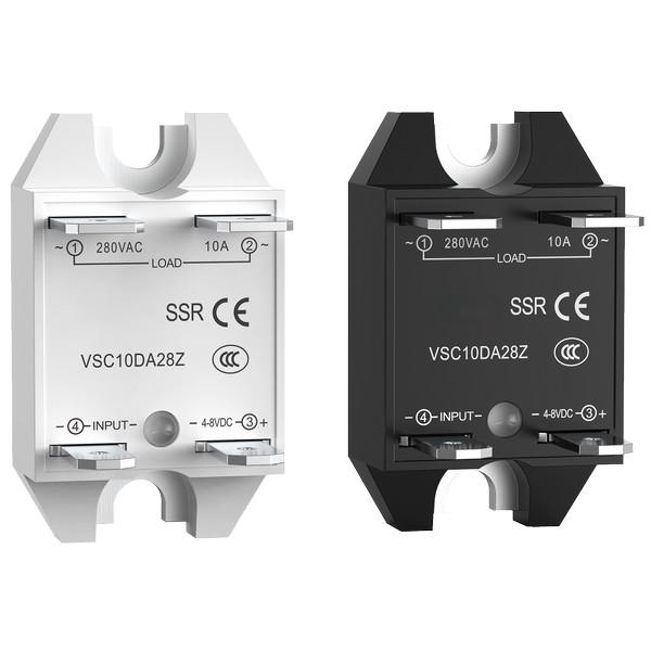
Solid state relay (SSR) is a contactless switching device implemented using microelectronics and power electronics technology. It abandons the mechanical contacts of traditional electromagnetic relays and uses semiconductor devices to complete on-off control. The VSC series single-phase solid-state relay is a high-performance product based on this technology, which is worth considering in situations where reliable, efficient, and long-life switch control is required

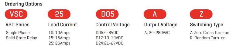
dvantages of VSC series single-phase solid-state relay products:
The VSC series single-phase solid-state relays integrate the core advantages of modern solid-state switching technology: long lifespan (no contact wear), high reliability (no sparks, vibration resistance), silent operation (no action noise), fast response (microsecond level switching speed), and excellent anti-interference ability. Its compact design facilitates installation and integration, and is well compatible with common logic level signals such as TTL, DTL, HTL, requiring only a small control signal to drive high current loads.

VSC series single-phase solid-state relay product features:
1. Wide range current and voltage adaptation:
We offer three rated current specifications of 10A, 15A, and 25A, with a working voltage range of 24-280VAC, to meet the power requirements of various single-phase loads.
2. Flexible conduction mode:
Supports two output modes: Zero Crossing or Random Turn On. Zero voltage conduction effectively reduces surge current and protects sensitive loads (such as incandescent lamps and heaters); The instantaneous derivative principle is applicable to control scenarios that require rapid response.
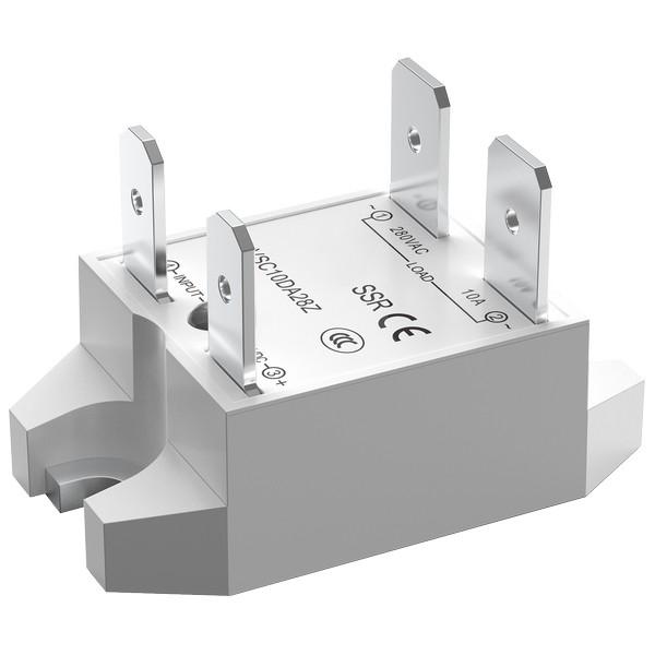
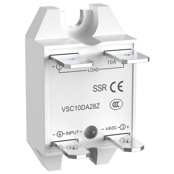
3. Convenient installation and connection:
The design emphasizes user friendliness, with clear and intuitive wiring terminals, a simple and efficient installation process, and effectively shortens project time
4. Clear status indication:
Built in LED input status indicator light, visually displaying the on/off status of control signals, facilitating on-site installation, debugging, and operation status monitoring.
5. Inherent advantages of solid-state technology:
No mechanical contacts, completely eliminating arcs, sparks, and mechanical wear; The switch action is quiet and silent, with strong resistance to electromagnetic interference (EMI) and shock and vibration, suitable for harsh industrial environments.

Product Selection

Control voltage Dutput voltage Rated operational current
10Amps 15Amps 25Amps
4-8VDC 280VAC”Z” VSC10D05AZ VSC15D05AZ VSC25D05AZ
4-8VDC 280VAC”R” VSC10D05AR VSC15D05AR VSC25D05AR
10-14VDC 280VAC”Z” VSC10D12AZ VSC15D12AZ VSC25D12AZ
10-14VDC 280VAC”R” VSC10D12AR VSC15D12AR VSC25D12AR
21-27VDC 280VAC”Z” VSC10D24AZ VSC15D24AZ VSC25D24AZ
21-27VDC 280VAC”R” VSC10D24AR VSC15D24AR VSC25D24AR

Input Specifications

Must Turn-Off Voltage   1VDC 1VDC 1VDC
Minimum Turn-On Voltage   4VDC 10DC 21VDC
Minimum Input Current   6mA 10mA 8mA
Maximum Turn-On Time [msec]   1/2Cycle 1/2Cycle 1/2Cycle
Maximum Turn-Off Time [msec]  1/2Cycle 1/2Cycle 1/2Cycle
Maximum Input Current   21mA 17.5mA 19mA
Description   D05 D12 D24
Control Voltage Range   4-8VDC 10-14VDC 21-27VDC

Output Specifications

Description 10Amps 15Amps 25Amps
Maximum l?t for fusing
[50/60Hz,1/2Cycle][A?sce]
100/95 165/160 338/326
Maximum load current [Adc] 10A 15A 25A
Maximum off-state leakage current
@rated voltage[mArms]
0.1 0.1 0.1
Maximum on-state voltage drop
@rated current [Volts]
1.3 1.3 1.3
Maximum surge current
[50/60Hz,1Cycle][Apk]
145/150 185/220 260/280
Minimum load current [mArms] 150 150 250
Minimum off-state dv/dt
aMaximum rated voltage [V/μsec
500 500 500
Minimum power factor
[at maximum  load]
0.7 0.7 0.7
Operating voltage [47-63Hz][Vrms] 24-280 24-280 24-280
Thermal resistance junction to case
[Rjc][°C/W]
3.0 2.2 0.9
Transient overvoltage [Vpk] 600 600 600
Know your supplier
Online store
On-time delivery rate
Response time
100.0%
≤4h
Company overview
Workplace: 1000m² Total staff: Highest Annual Export(usD): 300000000
Workplace: 1000m²
Total staff:
Highest Annual Export(usD): 300000000
Services
Business Type: Sales
Main Categories: Low Voltage Electrical Apparatus/Instrument meters/Production equipment/Tester/High Voltage Electrical Apparatus/Electrical fittings/Equipment Parts
Whole life care manager
Whole-life care management services for equipment procurement, use, maintenance, and after-sales, ensuring safe operation of electrical equipment, continuous control, and worry-free electricity consumption.
The equipment supplier has passed platform qualification certification and technical evaluation, ensuring compliance, professionalism, and reliability from the source.

Related Products

Related Knowledges

  • Faults and Handling of Single-phase Grounding in 10kV Distribution Lines
    Characteristics and Detection Devices for Single-Phase Ground Faults1. Characteristics of Single-Phase Ground FaultsCentral Alarm Signals:The warning bell rings, and the indicator lamp labeled “Ground Fault on [X] kV Bus Section [Y]” illuminates. In systems with a Petersen coil (arc suppression coil) grounding the neutral point, the “Petersen Coil Operated” indicator also lights up.Insulation Monitoring Voltmeter Indications:The voltage of the faulted phase decreases (in
    01/30/2026
  • Neutral point grounding operation mode for 110kV~220kV power grid transformers
    The arrangement of neutral point grounding operation modes for 110kV~220kV power grid transformers shall meet the insulation withstand requirements of transformer neutral points, and shall also strive to keep the zero-sequence impedance of substations basically unchanged, while ensuring that the zero-sequence comprehensive impedance at any short-circuit point in the system does not exceed three times the positive-sequence comprehensive impedance.For 220kV and 110kV transformers in new constructi
    01/29/2026
  • Why Do Substations Use Stones, Gravel, Pebbles, and Crushed Rock?
    Why Do Substations Use Stones, Gravel, Pebbles, and Crushed Rock?In substations, equipment such as power and distribution transformers, transmission lines, voltage transformers, current transformers, and disconnect switches all require grounding. Beyond grounding, we will now explore in depth why gravel and crushed stone are commonly used in substations. Though they appear ordinary, these stones play a critical safety and functional role.In substation grounding design—especially when multiple gr
    01/29/2026
  • Why Must a Transformer Core Be Grounded at Only One Point? Isn't Multi-Point Grounding More Reliable?
    Why Does the Transformer Core Need to Be Grounded?During operation, the transformer core, along with the metal structures, parts, and components that fix the core and windings, are all situated in a strong electric field. Under the influence of this electric field, they acquire a relatively high potential with respect to ground. If the core is not grounded, a potential difference will exist between the core and the grounded clamping structures and tank, which may lead to intermittent discharge.I
    01/29/2026
  • Understanding Transformer Neutral Grounding
    I. What is a Neutral Point?In transformers and generators, the neutral point is a specific point in the winding where the absolute voltage between this point and each external terminal is equal. In the diagram below, pointOrepresents the neutral point.II. Why Does the Neutral Point Need Grounding?The electrical connection method between the neutral point and earth in a three-phase AC power system is called theneutral grounding method. This grounding method directly affects:The safety, reliabilit
    01/29/2026
  • What’s the Difference Between Rectifier Transformers and Power Transformers?
    What is a Rectifier Transformer?"Power conversion" is a general term encompassing rectification, inversion, and frequency conversion, with rectification being the most widely used among them. Rectifier equipment converts input AC power into DC output through rectification and filtering. A rectifier transformer serves as the power supply transformer for such rectifier equipment. In industrial applications, most DC power supplies are obtained by combining a rectifier transformer with rectifier equ
    01/29/2026
Haven't found the right supplier yet? Let matching verified suppliers find you. Get Quotation Now
Haven't found the right supplier yet? Let matching verified suppliers find you.
Get Quotation Now
Send inquiry
+86
Click to upload file
Download
Get the IEE Business Application
Use the IEE-Business app to find equipment, obtain solutions, connect with experts, and participate in industry collaboration anytime, anywhere—fully supporting the development of your power projects and business.