• Product
  • Suppliers
  • Manufacturers
  • Solutions
  • Free tools
  • Knowledges
  • Experts
  • Communities
Search


Safety Challenges and Countermeasures for Transmission Towers and Insulator Strings in Rain and Snow

Wone Store
2yrs + staff 1000+m² US$300,000,000+ China

01 Safety Mechanisms of High-Voltage Transmission Towers

​**▍ Electric Shock Risk and Insulation Measures**​

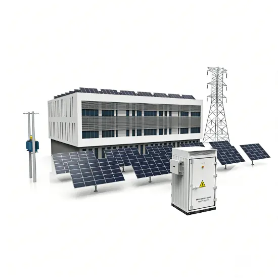
High-voltage transmission towers stand tall through wind and rain, carrying the vital task of power transmission, bearing the warning "High Voltage - Danger." This naturally raises the question: if you touch these towers, will you actually get an electric shock? Especially under adverse weather conditions like rain or snow, what happens?

In reality, we can start with the phenomenon of "high-voltage transmission towers" to delve into the safety mechanisms behind them. High-voltage lines use bare conductors, and the combination of supporting structures (towers/poles) and insulator strings isolates the risk of electric shock, ensuring safety. As discussed previously, high-voltage lines typically transmit power using bare conductors. As live conductors, they do indeed present an electric shock hazard. To ensure safety, a combined approach using supporting structures and insulator strings is employed. The towers lift the conductors high above ground, while the insulator strings provide effective electrical insulation between the conductors and the metal towers, thereby isolating this potential shock risk.

​**▍ Impact of Rain and Snow**​

However, when faced with rain or snow, the situation changes. At this point, we must consider that precipitation can degrade the insulating performance of the insulator strings, potentially forming conductive paths and increasing risk. During long-term outdoor operation, insulator strings inevitably accumulate various contaminants. Under the wetting effect of rain, these contaminants can gradually form conductive paths. Once the insulating path breaks down (flashover), the tower can become energized, creating a safety hazard. To mitigate this risk, designers meticulously configure the insulator strings on the towers to minimize the formation of such conductive rain-and-contaminant paths.

02 Insulator Design and Challenges

​**▍ Insulation Design and Risks**​

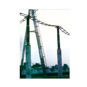
Even with precise insulator string design, as indicated by the red line in the figure above, forming a continuous conductive path is not easy – it requires intricate geometry and precise positioning. However, even this is insufficient. Even with maneuvering skill, ultimately, under severe weather conditions, ice or snow bridging may short-circuit insulators, significantly impairing insulation performance. This is especially true during thawing periods or under freezing rain. Because in the process of forming a continuous conductive path, the absence or disruption of any part can cause the entire path to fail. Imagine a freezing winter where a thick layer of ice and snow covers the line insulator strings. Would you worry that the ice/snow itself could conduct electricity? This possibility does exist. During severe ice accretion (heavy icing), ice bridging across the insulator string surface can cause short circuits, drastically reducing electrical strength. Particularly during thawing or freezing rain, water film formation on the insulator surface can lead to flashovers, further threatening the integrity of the conductive path (and causing failure).

​**▍ Prevention Strategies**​

To prevent ice-induced flashovers, two primary insulator string design strategies are typically employed, aiming to disrupt the formation of continuous ice:

  1. "V" String Configuration:​ Arranging insulator strings in a "V" shape significantly reduces the vertical inclination. This tilted design not only makes it difficult for ice sleeves to form continuously, thereby effectively preventing ice bridging, but also enhances the self-cleaning capability of the strings. Wind and gravity are more likely to shed light contaminants or small accumulations.

Using "V" Configuration and Alternating Disc Sizes ("Intercalation Strategy") to Enhance Ice Resistance, Though Failure May Occur in Extreme Cases

  1. Disc Size Alternation ("Intercalation Strategy"):​ Large-diameter insulator discs or large-diameter sheds are incorporated at specific intervals within the string. These larger surfaces effectively guide meltwater away during thawing, creating breaks in the ice profile and preventing the formation of a continuous ice bridge or conductive water film path along the entire string. This strategy significantly boosts the ice resistance of the insulator string, proactively preventing flashovers before they occur.

However, during extremely severe icing events where the insulator string becomes completely encapsulated, relying solely on the disc alternation strategy may not be sufficient to fully resolve the problem. Additional measures like de-icing might be necessary.

08/22/2025
Recommended
Solution for Medium-Voltage Motor Control and Protection Using Vacuum Contactor-Fuse (VCF) in a Coal Conveying System
Project BackgroundA coal conveying system comprises 15 belt conveyors driven by medium-voltage motors. The system operates under complex conditions, with motors often subjected to heavy loads and frequent starts. To address these challenges and achieve effective control and reliable protection during motor startup, the project comprehensively adopts Vacuum Contactor-Fuse (VCF) combination devices for the 6kV medium-voltage motor power distribution. This solution details the technical features,
ABB Vacuum Contactor KC2 Power Supply System Technical Transformation Plan
Issue Overview​The 10kV air compressor starting system of a company utilizes the ABB vacuum contactor KC2 as the control component for the operating circuit. The dedicated wide-voltage power supply module paired with this contactor presents the following issues:​Frequent failures: The power supply module fails to properly transition the voltage from 300V to 12V, resulting in fuse blowouts.​Poor heat dissipation: Enclosed installation of the module leads to insufficient heat dissipation, acceler
Dedicated Vacuum Contactor Solution for Port Shore Power Systems
I. Background and Challenges​Shore power systems have become core technical equipment for ports to reduce carbon emissions and noise pollution. However, these systems face two major challenges in the harsh operational environment of ports:​Severe Environmental Corrosion: High humidity and salt spray in port areas cause serious corrosion to metal components and enclosures of electrical equipment, significantly impacting electrical lifespan and operational reliability.​High Switching Requirements:
Vacuum Contactor Industrial Power Control Solutions
Application Background and Pain Point Analysis​In modern industrial manufacturing power control systems, traditional contactors exhibit significant limitations under specific operating conditions:• ​Frequent Start-Stop Operations: Traditional contactors have limited mechanical lifespan, with frequent operations leading to coil burnout and mechanical jamming.• ​Poor Adaptability to Harsh Environments: Contacts are prone to oxidation in dusty environments, resulting in increased contact
Seed Inquiry
Download
Get the IEE Business Application
Use the IEE-Business app to find equipment, obtain solutions, connect with experts, and participate in industry collaboration anytime, anywhere—fully supporting the development of your power projects and business.