• Product
  • Suppliers
  • Manufacturers
  • Solutions
  • Free tools
  • Knowledges
  • Experts
  • Communities
Search


What Tests Must a Qualified AIS Current Transformer Undergo?

Oliver Watts
Field: Inspection and testing
China

Hey everyone, I’m Oliver, a 10-year veteran in the power system industry. Today we’re going to talk about a very practical topic — how do you know if a current transformer (CT) used in Air Insulated Switchgear (AIS) is truly qualified? This isn’t just about meeting technical specs; it’s directly tied to equipment safety, grid stability, and accurate metering.Let’s dive in — based on my real-world experience.

Introduction

In substations or distribution systems, current transformers play a critical role. They convert high primary currents into manageable secondary signals for measurement, protection, and control.

To ensure they perform reliably under all conditions, a series of tests must be carried out — from factory testing to on-site commissioning and long-term maintenance.

So what are those essential tests?

Let me walk you through them step by step.

Part 1: Basic Performance Testing Before Factory Delivery
(1) Insulation Resistance Test

This is one of the most fundamental — yet crucial — tests.

  • Purpose: To check whether the insulation between the primary winding, secondary winding, and housing is intact.

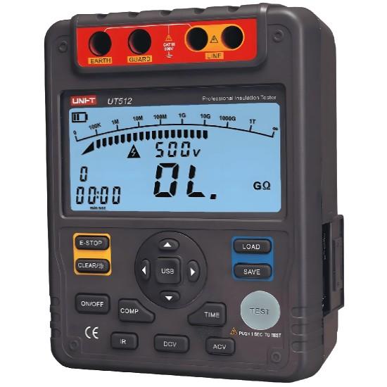
  • Method: Use a megohmmeter (insulation tester) to measure resistance.

  • Standard: Typically should be above 500 MΩ, though exact values depend on manufacturer specifications and standards like IEC or IEEE.

A low reading could indicate moisture ingress, aging insulation, or manufacturing defects.

(2) Power Frequency Withstand Voltage Test (Dielectric Test)

Also known as the "hi-pot" test.

  • Purpose: To verify that the CT can withstand high voltages without breakdown during normal operation or transient overvoltages.

  • Procedure: Apply a voltage several times higher than rated (e.g., 3 kV for a 1 kV-rated CT), usually for 1 minute.

  • What to Watch For: Any signs of arcing, flashover, or insulation failure.

This ensures the CT can handle electrical stress safely.

(3) Ratio Error Test

The core function of a CT is to accurately transform current.

  • Purpose: To confirm that the actual current ratio matches the nameplate value.

  • How It's Done:

    • Measure primary and secondary currents at various loads.

    • Calculate the error percentage.

  • Acceptable Range:

    • For metering CTs: ±0.5%

    • For protection CTs: ±1% or more, depending on application.

Accuracy matters — especially when billing or protection logic depends on it.

(4) Polarity Check

Polarity errors can cause serious issues, especially in differential protection circuits.

  • Purpose: To confirm the correct direction of current flow between primary and secondary windings.

  • Methods:

    • DC method: Briefly apply a DC voltage and observe the deflection on a voltmeter.

    • AC method: Use a standard CT to compare phase angles.

  • Best Practice: Always double-check after installation.

Don’t skip this — it’s easy to mess up and hard to catch later.

Part 2: Functional Testing After On-Site Installation
(1)Grounding Resistance Test

Proper grounding is essential for both safety and performance.

  • Tool: Ground resistance tester.

  • Target: Usually below 4 ohms, though stricter requirements may apply in sensitive environments.

  • Why It Matters: Poor grounding can lead to electric shock risks, equipment damage, or false tripping.

Especially important in outdoor AIS setups exposed to weather and environmental factors.

(2) Secondary Loop Continuity Test

Ensures there are no open circuits or loose connections in the secondary wiring.

  • Method: Use a multimeter to check for continuity across terminals.

  • Importance:

    • An open circuit can cause dangerously high voltages.

    • Loose connections may result in signal loss or overheating.

Never energize a CT with an open secondary!

(3) Temperature Rise Test

Overheating can degrade insulation and shorten the life of a CT.

  • Process: Run the CT at rated current for a set time and monitor temperature rise.

  • Limits: Must stay within specified thermal limits (e.g., 55K rise for Class B insulation).

  • Tools: Infrared thermography or embedded temperature sensors.

Helps identify poor contact points or inadequate cooling.

(4) Dynamic Response Test

Checks how well the CT responds to sudden changes in current, such as short circuits.

  • Method: Inject a simulated fault current and observe secondary output behavior.

  • Goal: Ensure fast, stable response for reliable protection triggering.

Crucial for applications involving relay protection systems.

Part 3: Periodic Maintenance During Long-Term Operation
(1) Partial Discharge Detection

Early signs of insulation degradation often appear as partial discharges.

  • Technique: Use ultrasonic or ultra-high frequency (UHF) sensors to detect discharge activity.

  • Frequency: At least once a year for critical systems.

  • Benefits: Early warning before major insulation failures occur.

Especially useful for aging equipment or units operating in harsh conditions.

(2) Accuracy Calibration

Over time, due to aging or environmental effects, CT accuracy may drift.

  • Approach: Remove key CTs periodically and recalibrate in a lab setting.

  • Interval: Varies by usage, but typically every 3–5 years for metering CTs.

Ensures continued compliance with standards and avoids billing disputes.

(3) Visual Inspection & Cleaning

Simple but effective.

  • Checklist:

    • Cracks or discoloration on housing

    • Corrosion on terminals

    • Dust buildup or blockage in ventilation

  • Action: Clean with dry cloth, tighten connections, replace damaged parts.

Combine with regular patrols for early detection of issues.

Final Thoughts

Testing a current transformer in air insulated switchgear isn’t something you can afford to take lightly. From basic factory checks to field commissioning and long-term monitoring — every step plays a vital role in ensuring safe, stable, and accurate operation.

Here’s a quick recap of the key tests:

If you're working with AIS CTs and have questions about any of these tests — or need help interpreting results — feel free to reach out anytime. I’d be happy to share more hands-on tips and troubleshooting techniques.

Let’s keep our CTs running strong — silently guarding our power systems behind the scenes.

— Oliver

Give a tip and encourage the author!
Recommended
High-Voltage Vacuum Contactor Testing and Maintenance Guide: Troubleshooting and Practical Tips
High-voltage vacuum contactors are currently widely used in various power equipment and other high-voltage motor equipment in China. The integrity and operating status of this component are crucial to the overall operation and safety of the machinery and equipment. Therefore, relevant inspection and maintenance personnel must carefully check this component in daily work, promptly identify problems, and conduct regular maintenance to ensure the normal progress of production.1. Principles for Insp
Oliver Watts
09/08/2025
Constant testing of high-voltage cable lines
1. Definition of High-Voltage Cable Line Constant TestingHigh-voltage cable line constant testing refers to the systematic measurement, using specialized instruments, of electrical parameters such as resistance, inductance, capacitance, and conductance before a cable line is commissioned or after major maintenance. The aim is to obtain fundamental data characterizing the electromagnetic properties of the cable, serving as a critical testing phase that provides accurate parameter support for powe
Oliver Watts
09/03/2025
Withstand voltage test of high-voltage cables
Withstand voltage test is an insulation test, but it is a destructive test that can reveal insulation defects difficult to detect in non-destructive testing.The test cycle for high-voltage cables is three years, and it must be conducted after non-destructive tests. In other words, the withstand voltage test is performed only after all non-destructive tests have been passed.Most high-voltage cables used today are cross-linked polyethylene (XLPE) cables, which can have large cross-sections and cov
Oliver Watts
09/03/2025
Analysis of Issues and Causes in Smart Meter Testing
1. Issues and Cause Analysis in Smart Electricity Meter TestingDuring the verification of smart electricity meters, inspections must be conducted on the meter’s appearance, as well as the clarity and integrity of nameplate markings. Additionally, careful checks are required for physical damage and whether the display can show digits completely. A power-on inspection is also necessary. If error codes appear on the display after power-up, faults should be identified and addressed according to the
Oliver Watts
09/01/2025
Seed Inquiry
Download
Get the IEE Business Application
Use the IEE-Business app to find equipment, obtain solutions, connect with experts, and participate in industry collaboration anytime, anywhere—fully supporting the development of your power projects and business.