Frequency division method for measuring grid-to-ground insulation parameters

The frequency division method enables the measurement of grid-to-ground parameters by injecting a current signal of a different frequency into the open delta side of the potential transformer (PT).
This method is applicable to ungrounded systems; however, when measuring the grid-to-ground parameters of a system where the neutral point is grounded via an arc suppression coil, the arc suppression coil must be disconnected from operation beforehand. Its measurement principle is shown in Figure 1.
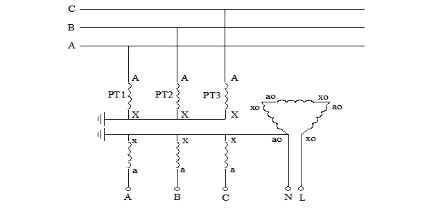 As shown in Figure 1, when a different-frequency current is injected from the open delta side of the PT, a zero-sequence current is induced on the high-voltage side of the PT. Since this zero-sequence current has the same magnitude and direction in the three phases, it cannot flow through the power supply side or the load side and can only form a loop through the PT and the ground capacitance. Therefore, the schematic diagram of Figure 1 can be further simplified to the physical model shown in Figure 2.

The heterofrequency current injected from the open delta side of the PT is a known quantity, and the voltage signal on this side can be directly measured.
After establishing the mathematical model shown in Figure 3 based on Figure 2, the equivalent phase-to-ground capacitance of the medium-voltage distribution network can be calculated by combining the transformation ratio of the PT, the injected current amplitudes and return voltage amplitudes corresponding to the two different frequencies, as well as the phase angle differences between the return voltage signals and injected current signals at these two frequencies.

Let θₘ be the phase angle difference between the voltage signal and the injected current signal, R be the phase resistance of the distribution network system, and Zₘ be the phase impedance of the distribution network system. Then:
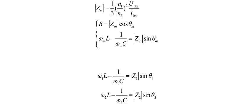
Simplify as follows:

The phase-to-ground capacitance of the distribution network system.

Based on the physical model in Figure 3, a corresponding mathematical model can be established. By detecting and measuring the signals, the three-phase-to-ground capacitance value (3C) can be measured. However, this method has certain inherent errors in principle.