What are the application and improvement directions of current transformers in power systems?

As a front - line power operation and maintenance worker, I deal with current transformers (CTs) daily. Having witnessed the popularization of new photoelectric CTs and tackled numerous faults, I’ve gained practical insights into their application and testing improvements. Below, I’ll share my on - site experience with new CTs in power systems, aiming for a balance between professionalism and practicality.
1. Application of New CTs in Power Systems
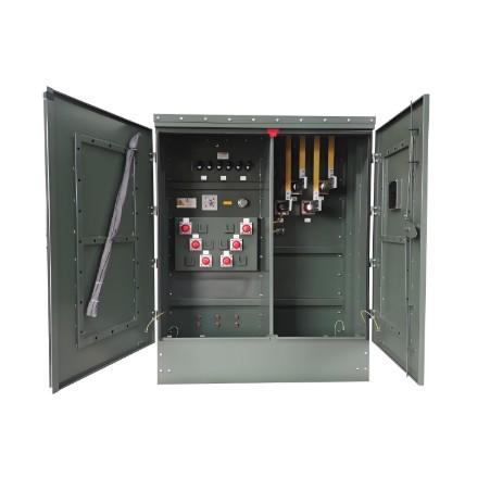
1.1 CTs in Power Systems
Most new CTs are photoelectric, categorized into iron - cored and coreless types. Iron - cored CTs, though prone to leakage current, electromagnetic saturation, and hysteresis in complex environments (e.g., high temperatures, strong magnetic fields), and with limited sensing head material precision (susceptible to nonlinear changes under extreme conditions), remain adaptable to modern high - voltage, large - unit power grids. Leveraging fiber optic sensing materials’ insulation advantages, they enable fiber optic light transmission, avoiding common issues of ordinary CTs—hence their widespread use in ultra - high - voltage transmission lines.
In practice, I’ve seen ordinary CTs suffer erratic data under strong electromagnetic interference, while photoelectric CTs restore stability—highlighting the new CTs’ practical value.
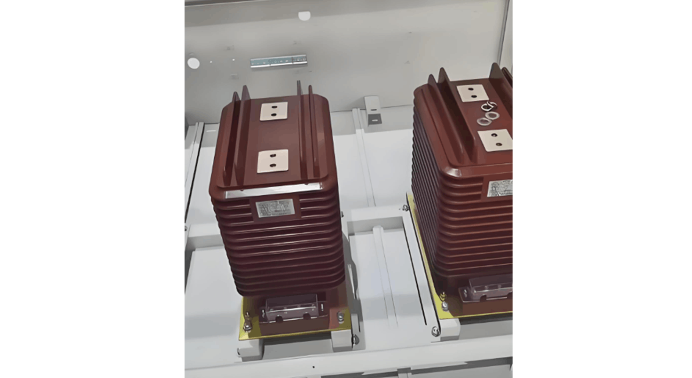
1.2 Protecting Large Generator Sets
Large generator sets (e.g., generators, main transformers) demand high transient performance from CTs. Previously plagued by transient saturation and remanence, new CTs now resolve these issues. Notably, 500kV “iron - cored with air gap” CTs boast high excitation impedance, providing stable protection for units, preventing transient saturation and remanence.
For instance, Huayi Electric Power’s TPY - level CTs for 300–600MW units, selected for transient characteristics and remanence limitation, ensure “no maloperation outside protection zones and correct tripping inside”. During unit protection commissioning, these CTs reliably suppress non - periodic short - circuit current components, avoiding protection misfires.
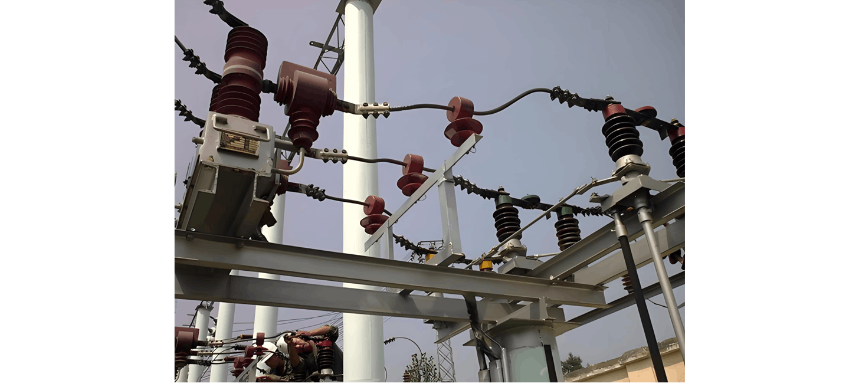
1.3 Automatic Relay Protection
Relay protection acts as the power grid’s “emergency doctor”, with CTs as its “stethoscope”. As grid automation advances, relay protection must evolve—CTs’ automatic adaptability directly impacts the system’s intelligence.
In faults, CTs must swiftly transmit current signals to protection devices for accurate fault isolation. New CTs offer faster response and precision, aligning with smart grid demands—critical for power automation.
2. CT Testing Improvements (Front - line Solutions)
With CT specifications ranging 20A–720A, our team developed an improved testing scheme to standardize processes, reduce human error, and simplify preparation.
2.1 Test Scheme Design
Focused on “integration + precision”, we use a dedicated single - phase current source for tested CT phases, switch current ranges via a conversion unit, monitor input with a standard meter (A1), and integrate phase angle measurement, standard CTs, conversion units, and meters into a test bench—streamlining tests.
(1) Current Source Selection
Abandoning unstable generator - set signal sources, we adopt a high - quality intermediate - frequency power supply paired with an auto - transformer and current booster to create a constant - current source (0–800A output), covering all AC CT tests and resolving primary - side current fluctuations.
(2) Test Line Principle
The closed loop “auto - transformer → current booster → standard CT → tested CT → intermediate - frequency power supply” operates at ~120V (intermediate - frequency output). Current adjustment relies on the auto - transformer (fixed current - booster ratio). To minimize fluctuations, the current booster output is short - circuited with a copper bus bar (shortened for less heat, stable current, and energy savings).
Passing the same current through all three phases of the tested CT reduces phase - to - phase current differences and boosts test efficiency—proven effective in batch testing.
3. Conclusion (Front - line Insights)
CT fault diagnosis is critical and systematic. As front - line staff, mastering CT principles and following protocols is essential—safety first! Always cut power before diagnosis/troubleshooting to avoid risks.
New CTs enhance grid operation and maintenance, but testing/diagnosis knowledge must keep pace. Understanding application scenarios and implementing test improvements ensures CTs serve as the power grid’s “loyal guards”.