• Product
  • Suppliers
  • Manufacturers
  • Solutions
  • Free tools
  • Knowledges
  • Experts
  • Communities
Search


Must DC circuit breakers always be bipolar?

James
Field: Electrical Operations
China

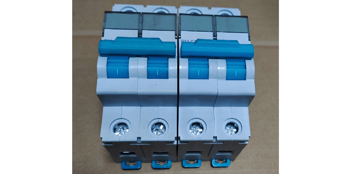
For a 24V switch-mode power supply branch, I used a single-pole DC circuit breaker, with the negative pole subjected to equipotential bonding (previously, I even directly used AC breakers as substitutes—the main difference being arc-extinguishing performance, but how significant can the arc be in a few-amp low-current short circuit?).

During a design review, an expert stated that DC circuit breakers must be bipolar, arguing that DC has positive and negative poles, unlike AC!

I'm puzzled—where is this regulation specified? Later, I wondered, why would manufacturers even produce single-pole versions? What is the rationale for requiring switching of the negative pole as well? According to available information, if a DC breaker is connected in reverse, the primary impact should only be on arc-extinguishing performance. Also, when I mentioned that the negative pole is equipotentially bonded, another expert claimed that "equipotential" doesn't apply to DC systems—only to AC. Is that true? It's strange—many sensors clearly mark their power supply negative terminal with the "GND" symbol.

For the incoming PE (protective earth) wire in the electrical cabinet, I directly used the PE green-yellow terminal on the mounting rail, but was told it's not acceptable and must be connected to a dedicated grounding busbar. It's hard to question the experts we've invited, especially those from the maritime field—marine applications are quite special, right?

image.png

User A's View:
Probably just being overly cautious. DC arc extinction differs from AC, but for low-voltage circuits, it might not be such a big concern. In my opinion, if it's not a critical application, a single-pole breaker, as long as it's reliable and won't cause contact welding, should be acceptable. Marine electrical systems primarily emphasize fire and safety. So safety must be prioritized.

User B's View:
In special cases, such requirements may be stricter. The intent is likely to ensure both poles are disconnected. If 0V is grounded, there could be risks of high-voltage intrusion, causing problems.

User C's View:
I relate to the point about the incoming PE wire. I directly used the PE terminal on the rail, but was told it's not allowed and must go to a grounding busbar. I understand this—it's a code requirement to ensure reliable and safe grounding.

User D's View:
Don't blindly follow outdated standards. I believe that any conductor carrying current or voltage should be controllable and interruptible. Standards from decades ago aren't necessarily safe today. Technology advances, and so should some standards.

User E's View:
For specified DC loads, polarity (+/-) is always clearly marked—reversing connections can lead to serious consequences. I'm not sure how exactly equipotential bonding is implemented, but I once modified an American machine where they kept saying the PLC wasn't sending signals, causing disputes and even involving the equipment department head. He simply used a multimeter—one probe on the chassis, one on the terminal—and concluded to "check the downstream side" (it turned out the software had disabled it). The issue was resolved by implementing equipotential bonding. Since you're dealing with marine applications, just follow the experts' recommendations.

User F's View:
If you use a bipolar breaker, it implies the negative terminal is not grounded—i.e., an isolated system. In such cases, a positive-to-ground short won't immediately cause a trip. The method of grounding the negative pole and using equipotential bonding isn't suitable for all situations. For equipment that can stop immediately, this method can help locate fault points and resolve issues. However, it's inappropriate for applications like medical or lifting equipment. Also, experts aren't omnipotent—they're only deeply familiar with certain areas. If you specialize deeply in a field, you can become an expert too.

If you have other suggestions or insights, feel free to share and discuss!

Give a tip and encourage the author!
Recommended
Mismatched AC Contactor Sizing? These 4 Typical Issues You Must Not Ignore – Click to View Solutions
AC contactors (with the electrical schematic code KM) are core electrical devices used to control the connection/disconnection between power supplies and loads in circuits, and they are also common equipment that electricians need to work with regularly. In practice, it is not uncommon to find that some peers make mistakes in selecting AC contactors, leading to improper sizing and subsequent persistent issues. Here, four of the most typical common mistakes are highlighted for reference.I. Over-R
James
09/11/2025
Proper Installation of AC Contactors | A Practical Guide to Avoid Burning and Misoperation, Master It in One Article
AC contactors are widely used for switching and controlling power circuits. They use main contacts to open and close circuits, and auxiliary contacts to execute control commands. Main contacts typically only have normally open contacts, while auxiliary contacts often have two pairs of contacts with normally open and normally closed functions. Small-sized contactors are also frequently used as intermediate relays to work with main circuits, thereby achieving the function of remote control or cont
James
09/11/2025
Technical Analysis of 220 kV High-Voltage Cable Construction in Winter
1.Work Environment Requirements and Safeguard MeasuresBased on technical requirements for cable equipment storage, laying, transportation, laying, transposition, testing, and cable terminations, the project owner and construction units have conducted extensive trials and implemented protective measures regarding ambient temperature, humidity, bending radius, traction control, and route optimization. These measures ensure high-voltage cable quality and on-site safety under harsh winter conditions
James
09/03/2025
Considerations and Recommendations for Flame-Retardant Selection of High-Voltage Cables
1.Flame-Retardant Cable Classification StandardsThe flame-retardant standard system is divided into two main categories. The first category follows the "Classification of Burning Behavior for Electric and Optical Fiber Cables" GB 31247. Cables complying with this standard system are widely used in densely populated areas such as high-speed railways and subways. This standard imposes strict requirements on parameters such as smoke density, heat release, and total smoke production, and cables typi
James
09/03/2025
Seed Inquiry
Download
Get the IEE Business Application
Use the IEE-Business app to find equipment, obtain solutions, connect with experts, and participate in industry collaboration anytime, anywhere—fully supporting the development of your power projects and business.