• Product
  • Suppliers
  • Manufacturers
  • Solutions
  • Free tools
  • Knowledges
  • Experts
  • Communities
Search


Distribution transformer calculations – MS Excel Spreadsheet

Dyson
Field: Electrical Standards
China

Four Fast Transformer Calculations

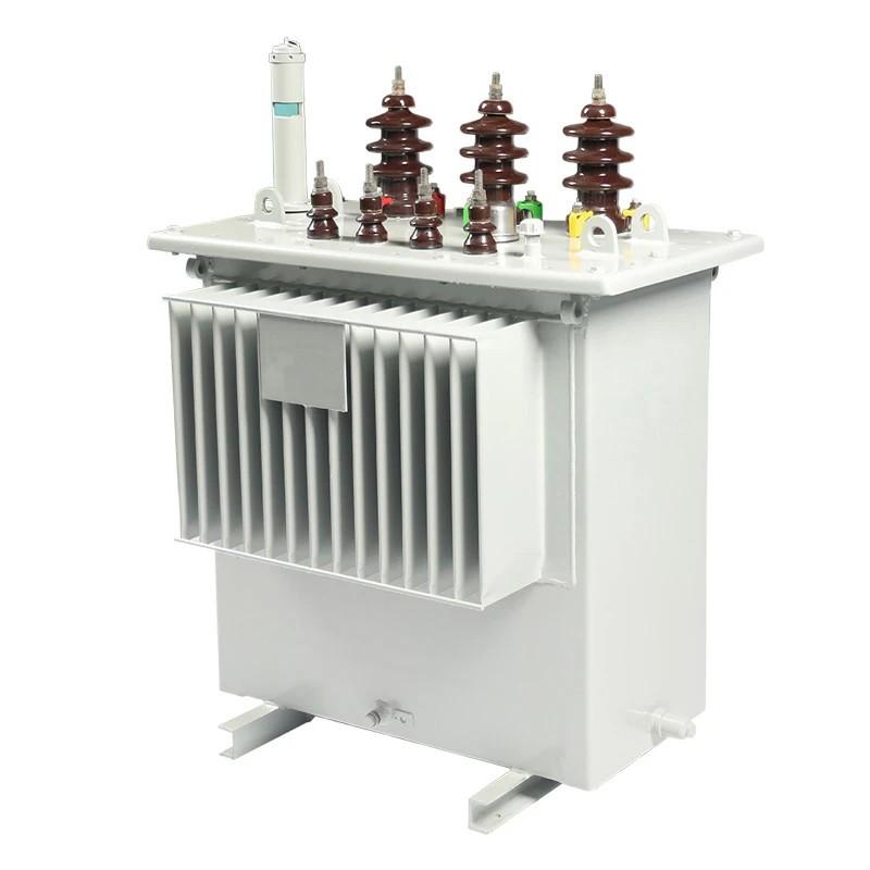
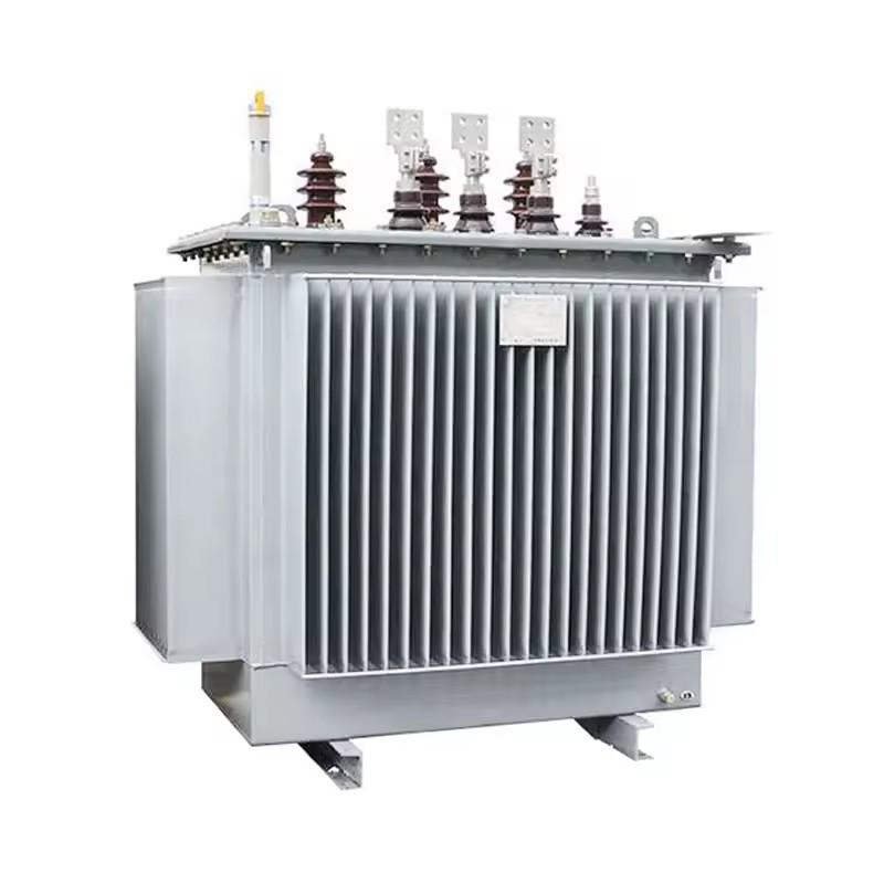
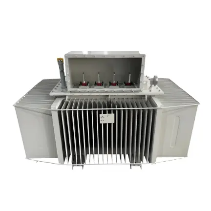
The distribution transformer calculations spreadsheet enables rapid computations for the following: ascertaining the MV/LV transformer rating, calculating the rating of the overcurrent protection device on the low - voltage side of the transformer, determining the prospective short - circuit current, and computing the sizes of natural ventilation openings required for the transformer room.
Determining the MV/LV Transformer Rating
Input Parameters:
  • Primary Rated Voltage (kV)
  • Secondary Rated Voltage (kV)
  • Maximum Demand Load (kW)
  • Corrected Power Factor
  • Transformer Type
  • Permissible Loading Percentage (%)
  • Nearest Standard Transformer Rating (kVA)

Calculating the Rating of Overcurrent Protection Device on the Low - Voltage Side of the Transformer

Calculating the prospective short - circuit current on the low - voltage side of the transformer

Calculating the sizes of natural ventilation openings required for the transformer room.


Give a tip and encourage the author!
Recommended
Key Technologies of Low-Voltage DC Solid-State Circuit Breakers
1 Technical Challenges1.1Stability of Device ParallelingIn practical applications, the current-carrying capacity of a single power electronic device is relatively limited. To meet high-current requirements, multiple devices are often connected in parallel. However, parameter variations between devices—such as slight differences in on-resistance and threshold voltage—can cause uneven current distribution during parallel operation. During switching transients, parasitic inductance and capacitance
Dyson
09/02/2025
Bridge-Type Fault Current Limiter | Superconducting & Solid-State
1 Bridge-Type Superconducting Fault Current Limiter1.1 Structure and Operating Principle of the Bridge-Type SFCLFigure 1 shows the single-phase circuit diagram of the bridge-type SFCL, which consists of four diodes D₁ to D₄, a DC bias voltage source V_b, and a superconducting coil L. A circuit breaker CB is connected in series with the limiter to interrupt the fault current after it has been limited. The bias source V_b provides a bias current i_b to the superconducting coil L. The voltage of V_
Dyson
08/25/2025
What should be paid attention to in the design of low-voltage pole-mounted circuit breakers?
Low-voltage pole-mounted circuit breakers are critical protective and control devices in power systems, whose design and operation directly affect system safety and reliability. Their design must comprehensively address environmental adaptability, electrical parameter coordination, and actuator selection to ensure stable operation under diverse conditions. During operation, strict adherence to safety protocols, regular maintenance, and proper handling of exceptional situations are essential to p
Dyson
08/21/2025
Steep-Front Impulse Breakdown of HTV-Coated Composite Porcelain Insulators: Mechanisms, Testing, and Simulation
Porcelain and glass insulators exhibit excellent insulation performance and mechanical strength, but are prone to pollution flashover under severe contamination, threatening the stable operation of power grids. To enhance the pollution flashover resistance of external insulation, manufacturers commonly apply room-temperature vulcanized silicone rubber (RTV) coatings with superior hydrophobicity and hydrophobicity transfer properties onto insulator surfaces, thereby reducing flashover risks. Init
Dyson
08/20/2025
Related Products
Seed Inquiry
Download
Get the IEE Business Application
Use the IEE-Business app to find equipment, obtain solutions, connect with experts, and participate in industry collaboration anytime, anywhere—fully supporting the development of your power projects and business.