1. Electric Shock Risk Prevention and Control
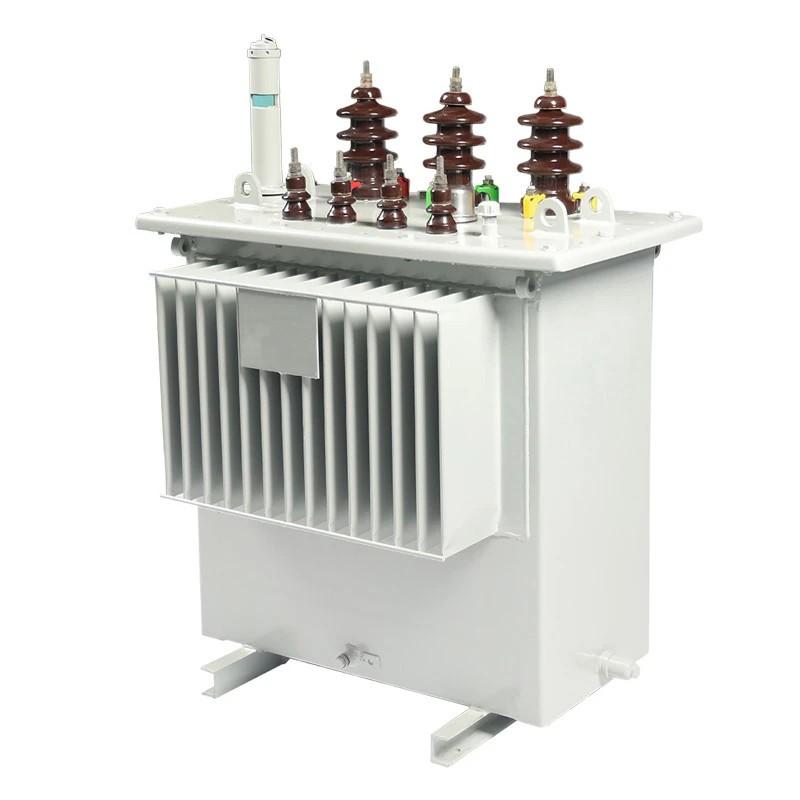
According to typical design standards for distribution network upgrades, the distance between the transformer’s drop-out fuse and the high-voltage terminal is 1.5 meters. If a crane is used for replacement, it is often impossible to maintain the required minimum safety clearance of 2 meters between the crane boom, lifting gear, slings, wire ropes, and the 10 kV live parts, posing a severe risk of electric shock.
Control Measures:
Measure 1:
De-energize the 10 kV line segment from the drop-out fuse upward and install grounding wires. The outage scope should be determined based on the location of pole-mounted switches, minimizing disruption while ensuring safety.
Measure 2 (Live-Line Work):
Perform live-line operations to disconnect the upper lead of the drop-out fuse from the 10 kV line. Install a grounding wire at the fuse’s upper terminal before using a crane to replace the transformer. Maintain ≥2 m clearance between all crane components (boom, hook, ropes, load) and live parts. Assign a dedicated safety supervisor, and ground the crane body with ≥16 mm² stranded copper wire.
Measure 3 (Forklift Option):
Where terrain permits, use an appropriately sized forklift considering transformer weight and platform height. Limit lift height to ensure ≥0.7 m clearance from the drop-out fuse. Assign a supervisor and ground the forklift with ≥16 mm² stranded copper wire.
Measure 4 (Specialized Replacement Device):
If the 10 kV line cannot be de-energized and live-line work is not feasible, use a modified all-terrain transformer replacement device. Maintain ≥0.7 m clearance from the fuse, assign a supervisor, and ground the device’s metal enclosure with ≥16 mm² stranded copper wire.

Measure 5 (Chain Hoist Method):
When no machinery can access the site, use a chain hoist. Suspend it within the protection zone of the HV-side grounding wire, ensuring ≥0.7 m clearance from live parts above the fuse. Assign a dedicated supervisor.
Measure 6 (Reduced Clearance Crane Work):
If crane-to-live-part distance is between 0.7 m and 2.0 m, develop a special construction plan with enhanced safeguards (e.g., insulated ropes to secure loads, rigid insulating barriers). Obtain approval from the county-level unit’s deputy director before execution. Assign a supervisor.
Note: A few transformers are installed inside distribution rooms, making crane use impossible. In such cases, manual replacement (using steel pipes or channels under the transformer, levered with crowbars and ropes) is employed. Maintain ≥0.7 m clearance from 10 kV live parts at all times, with a dedicated supervisor.
Measure 7 (Manual Replacement):
Open the drop-out fuse, install grounding wires on both HV and LV sides. Transport steel pipes/channels in a horizontal position. Ensure all tools and personnel maintain ≥0.7 m clearance from live equipment. Assign a supervisor.
Additional Scenarios:
For older, un-upgraded transformers where the fuse-to-terminal distance is ~3 meters:
Measure 8: Open the fuse, use a properly sized crane, maintain ≥2 m clearance from live parts above the fuse, supervise, and ground the crane (≥16 mm² copper wire).
If an isolator switch (knife switch) is installed between the fuse and the 10 kV line:
Measure 9: Sequentially open the drop-out fuse and isolator. Use a crane with ≥2 m clearance from live parts above the isolator. Supervise and ground the crane (≥16 mm² copper wire).
Even when the 10 kV line is de-energized, crane operations may approach or cross 0.4 kV lines:
Measure 10: De-energize, test for voltage, and ground any 0.4 kV lines that are within <1.5 m of crane paths or that must be crossed.
2. Mechanical Injury Risk Prevention
2.1 Crane Operations
Inspect hydraulic system, wire ropes, hooks, and brakes before use.
Operate only on level, solid ground—never over culverts or underground utilities.
Establish a dedicated exclusion zone with safety barriers; prohibit unauthorized entry.
No personnel allowed under boom or suspended loads.
Assign a certified signal person to direct operations.
2.2 Forklift Operations
Check engine, steering, and braking systems before use.
Operate on firm, level surfaces per manufacturer guidelines.
Set up barriers; restrict access.
Use a designated spotter.
2.3 Excavator Operations
Prohibit riding on buckets, booms, tracks, or cab roofs.
Clear work area of non-essential personnel.
Operator must sound horn or give warning signal before moving.
Assign a spotter.
2.4 Custom-Built Equipment
Pre-use inspection of all mechanical and control systems.
Isolate work zone with barriers.
Assign a supervisor.
2.5 Chain Hoists
Inspect hooks, chains, gears, and brakes before lifting.
No personnel under suspended loads.
Use a designated rigger/supervisor.
3. Protection Against Falling Object Injuries
Risks exist during both mechanical and manual operations due to dropped tools or materials.
Control Measures:
All personnel must wear properly fitted hard hats (chin strap fastened, headband adjusted).
Prohibit standing or passing directly below work areas.
Use tool pouches for elevated work.
Secure large items to poles/towers.
Use tethered ropes to pass tools/materials vertically.
Avoid simultaneous work at multiple heights whenever possible.
4. Fall-from-Height Prevention
4.1 Pole Climbing
Before climbing, inspect ladders, step bolts, foot grips, harnesses, backup lanyards, single/dual hooks, and anti-fall belts. Ensure all have valid test labels. Perform impact tests.
When using step bolts: always pair with single-hook dual-loop system.
When using foot grips: always use anti-fall encircling belt.
When climbing fixed ladders: use dual-lanyard system.
Have a second person stabilize portable ladders.
4.2 Working at Height
Wear a full-body harness at all times, connected to a backup lanyard or self-retracting lifeline.
Never work without fall protection—protection must be continuous throughout the task.
5. Traffic Accident Prevention
Replacement sites are often near roads or village lanes, posing traffic risks.
Control Measures:
Place “Slow Down” warning signs at least 50 meters (or 150 meters per traffic regulations, adjusted based on traffic volume and road speed) upstream and downstream of the work zone—never at the work site itself.
When moving heavy equipment, assign a traffic controller to manage vehicle flow.