| Brand | RW Energy |
| Model NO. | 0 to 500Hz 200V to 690V engineering frequency converter |
| Rated frequency | 50/60Hz |
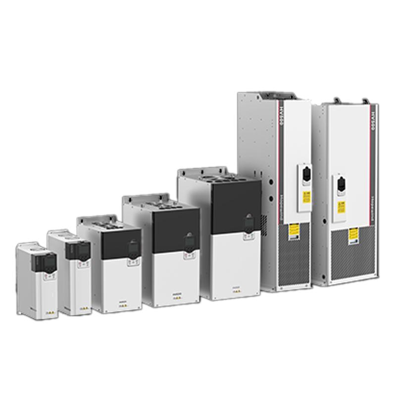
| Series | HV500 |
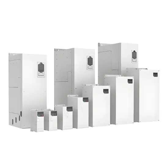
Overview
HV500 series is an engineering single frequency converter with three product concepts: "universal", "easy to use" and "durable" for mid-to-high-end industrial single transmission applications on the basis of inheriting the excellent control performance of HD2000 engineering frequency converters. It can be widely used in metallurgy, nonferrous metals, chemicals, electric power, rubber, cement, lifting, papermaking, mining, textile and municipal industrial occasions.
Performance characteristics
Durability
Mechanical vibration level 3M3
Independent air duct design
Automatic spraying of conformal paint
Built-in dynamic junction temperature model to help product safety application
Versatility
Certified by a number of international standards and compliant with RoHS Directive
Support V/F, OLVC, CLVC control
Support multiple communication protocols
Support asynchronous and permanent magnet synchronous motors
Ease of use
Supports external 24V DC input power supply
Built-in brake unit can be used to save installation controls
Book-type design supports seamless side-by-side installation
Meet a variety of needs
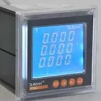
LCD display panel as standard to improve user experience
With master-slave control function
Expandable communication card, code disk card, voltage detection card
Excellent performance
Zero-speed hover
Torque response of 1-3ms
Excellent robustness
Very low dynamic drop and dynamic drop equivalent
Accurate off-line/in-line motor model recognition
Quick debugging software in the background
Powerful and easy to use
Features such as parameter setting, real-time oscilloscope, fault recording, and event recording
Main parameters
| project | Specifications and technical data |
|
Power input and output |
Input voltage Uin |
200V (-15%) ~ 240V (+10%) three-phase, 380V (-15%)~480V (+10%) three-phase, 500V (-15%)~690V (+10%) three-phase |
Input power frequency |
50Hz/60Hz±5% |
|
Input voltage imbalance |
≤3% |
|
Output voltage |
0V~input voltage |
|
Output frequency |
0Hz~500Hz |
|
Power range |
2.2kW~560kW |
|
Mainly control performance |
Motor type |
Asynchronous motor/synchronous motor |
Control mode |
V/F, OLVC (Open-Loop Vector Control), CLVC (Closed-Loop Vector Control) |
|
speed regulation range |
1:10 V/F; 1:100 OLVC; 1:1000 CLVC |
|
Start torque |
VF:100%(0.5Hz);OLVC:150%(0.5Hz);CLVC:180%(0Hz) |
|
Torque accuracy |
≤5%, under vector control mode |
|
Torque pulsation |
≤5%, under vector control mode |
|
Steady speed accuracy |
OLVC 0.2%; CLVC 0.01% |
|
Torque response |
<5ms, under vector control |
|
Dynamic drop equivalent |
OLVC<0.5%*s; CLVC<0.3%*s |
|
Increase and deceleration time |
0.0s~3200.0s;0.0min~3200.0min |
|
Torque increase |
0.0%~30.0% |
|
Overload capacity |
150% 1min/5min for heavy-duty applications; Light load application 110% 1min/5min |
|
V/F curve |
Various methods: linear VF curve, 5 torque reduction characteristic curve methods; (2.0 powers, 1.8 powers, 1.6 powers, 1.4 powers, 1.2 powers) |
|
User-defined VF curves |
||
Input frequency resolution |
The digital setting is 0.01Hz, and the analog setting is 0.01Hz |
|
Main control functions |
acceleration and deceleration curves |
Straight line, S-curve |
Multi-speed operation |
16 speed operation is achieved through the control terminal |
|
Automatic Voltage Regulation (AVR) |
When the grid voltage changes within a certain range, it can automatically keep the output voltage constant |
|
Fixed length control |
Given length control |
|
Built-in PID |
It can be easily formed as a closed-loop control system |
|
Enhancements |
Free function blocks |
|
Input and output functions |
Frequency setting method |
Keyboard given, UP/DOWN terminal, multi-speed give, terminal pulse given, communication |
Analog input terminals |
AI1: 0V~10V/-10V~10V; AI2 : 0V~10V/0(4)mA~20mA |
|
Digital input terminals |
DI1-DI6, 6 programmable digital inputs, optocoupler-isolated, drain/source compatible inputs |
|
Digital input and output terminals |
DIO1: Fast pulse output, normal input/output; DIO2: Fast pulse input, normal input/output |
|
Analog output terminals |
2 channels 0V~10V/0(4)mA~20mA |
|
Relay output |
2-way contact type FormC |
|
Motor temperature detection |
Support type PT100/PT1000/KTY84 |
|
STO interface |
SIL3/PLe level safety torque shutdown function |
|
communication |
Communication protocol |
Modbus RTU (standard), Profibus, CANopen, profinet, Devicenet, ControlNet |
Usage environment |
altitude |
no derating is required within 2000 meters above sea level; At an altitude of 2000 meters ~ 4000 meters, the current must be reduced by 1% for every 100 meters of elevation |
Ambient temperature |
-25°C~+40°C (40°C to 55°C derating is allowed) |
|
humidity |
15%~95%, no condensation |
|
vibration |
3M3,IEC60721-3-3 |
|
Storage temperature |
-40℃~+70℃ |
|
Place of use |
Indoors, there is no direct sunlight, no flammable and corrosive gases, liquids and conductive particles |
|
Options: |
code disk card, communication expansion card, voltage detection card |
|
Protection function |
Short circuit, overcurrent, overload, overvoltage, undervoltage, phase loss, overheating, external faults, etc |
|
efficiency |
5.5kW~22kW:≥93%; 30kW and above: ≥95% |
|
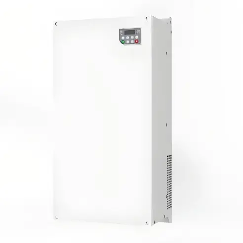
Installation method: |
Loading machines and containers |
|
Protection level |
IP20 |
|
Cooling method |
Forced wind cooling |
|
Supports master-slave synchronous control, allowing multiple motors to start and stop simultaneously. The rollers on the production line run synchronously without jamming. It also supports switching between 4 sets of motor parameters, allowing one frequency converter to handle multiple devices, saving space and money.
There is a power outage restart function! After a power outage, the power grid will automatically resume stable operation without manual intervention. The factory experiences power outages at night and automatically starts working as soon as the power is restored in the morning, saving labor and increasing efficiency, ensuring uninterrupted production.
Under closed-loop vector control, the stable speed accuracy is 0.01% (CLVC), which is 10 times higher than that of ordinary frequency converters. The conveyor belt runs super smoothly, and the products will not fall off. The precision is as high as in a laboratory, and the production quality is more stable.