• Product
  • Suppliers
  • Manufacturers
  • Solutions
  • Free tools
  • Knowledges
  • Experts
  • Communities
Search


Loss evaluation in transformers based on IEC 60076

Dyson
Field: Electrical Standards
China

I. Definitions of Losses in IEC 6007

IEC 60076-1 (General Requirements) and IEC 60076-7 (Loading Guidelines) specify two core types of losses:

No-load Loss (P0)

Definition: Losses measured when the primary winding is energized at rated voltage and the secondary winding is open-circuited (dominated by core losses).

Test Conditions

  • Measured at rated frequency and voltage (typically sinusoidal power frequency).

  • Corrected to reference temperature (75°C for oil-immersed transformers, 115°C for dry-type).

Load Loss (Pk)

Definition: Losses measured when the secondary winding is short-circuited and rated current flows through the primary winding (dominated by copper losses).

Test Conditions:

  • Measured at rated current and frequency.

  • Corrected to reference temperature (75°C for oil-immersed; varies for dry-type based on insulation class).

II. Testing and Calculation of Losses

No-load Loss Test (IEC 60076-1 Clause 10)

Method

  • Direct measurement using a power analyzer (instrument losses must be subtracted).

  • Test voltage: rated voltage ±5%, with the lowest value used.

Temperature Correction Formula:

Bref: Flux density at reference temperature; B test : Measured flux density.

2. Load Loss Test (IEC 60076-1 Clause 11)

Method:

  • Measured during short-circuit impedance testing.

  • Test current: rated current; frequency deviation ≤ ±5%.

Temperature Correction Formula (for copper windings)

Tref: Reference temperature (75°C); T test : Winding temperature during testing.

Key Parameters and Tolerances

Loss Tolerances (IEC 60076-1 Clause 4.2):

  • No-load loss: +15% allowed (measured value must not exceed guaranteed value).

  • Load loss: +15% allowed (measured value must not exceed guaranteed value).
    Stray Losses:

Losses caused by leakage flux in structural components, evaluated via high-frequency component separation or thermal imaging.

Energy Efficiency Classes and Loss Optimization

Per IEC 60076-14 (Energy Efficiency Guidelines for Power Transformers):

Total Losses (P total):

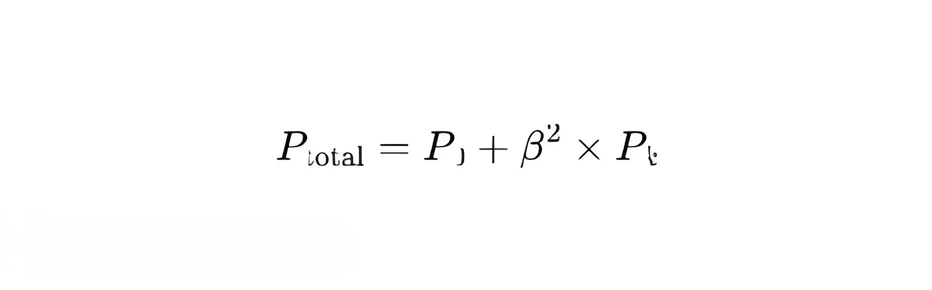
β: Load ratio (actual load / rated load).

Efficiency Classes (e.g., IE4, IE5) require total losses reduced by 10%~30%, achieved via:

  • High-permeability silicon steel (reduces no-load losses).

  • Optimized winding design (minimizes eddy current losses).

Practical Application Example

Case: 35kV Oil-Immersed Transformer (IEC 60076-7)

Rated Parameters:

  • Capacity: 10 MVA

  • Guaranteed no-load loss: 5 kW

  • Guaranteed load loss: 50 kW (at 75°C).

Test Data:

No-load loss: 5.2 kW (within +15% tolerance → 5.75 kW limit).

Load loss (tested at 30°C):

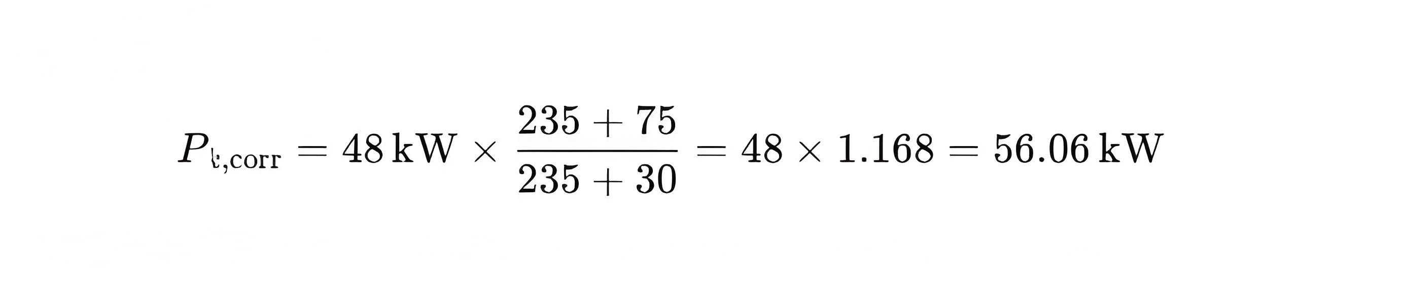
Conclusion: Load loss exceeds tolerance? Verify against 50 × 1.15 = 57.5 kW.

VI. Common Issues and Considerations

Ambient Temperature:

Tests must be conducted between -25°C to +40°C; corrections required outside this range.

Harmonic Losses:

Evaluate additional harmonic losses under non-sinusoidal loads per IEC 60076-18.

Digital Testing:

Use IEC 61869-calibrated sensors for accuracy.

Give a tip and encourage the author!

Recommended

Distribution Equipment Transformer Testing, Inspection, and Maintenance
1.Transformer Maintenance and Inspection Open the low-voltage (LV) circuit breaker of the transformer under maintenance, remove the control power fuse, and hang a “Do Not Close” warning sign on the switch handle. Open the high-voltage (HV) circuit breaker of the transformer under maintenance, close the grounding switch, fully discharge the transformer, lock the HV switchgear, and hang a “Do Not Close” warning sign on the switch handle. For dry-type transformer maintenance: first clean the porcel
12/25/2025
Design Principles for Pole-Mounted Distribution Transformers
Design Principles for Pole-Mounted Distribution Transformers(1) Location and Layout PrinciplesPole-mounted transformer platforms should be located near the load center or close to critical loads, following the principle of “small capacity, multiple locations” to facilitate equipment replacement and maintenance. For residential power supply, three-phase transformers may be installed nearby based on current demand and future growth projections.(2) Capacity Selection for Three-Phase Pole-Mounted Tr
12/25/2025
Risk Identification and Control Measures for Distribution Transformer Replacement Work
1.Electric Shock Risk Prevention and ControlAccording to typical design standards for distribution network upgrades, the distance between the transformer’s drop-out fuse and the high-voltage terminal is 1.5 meters. If a crane is used for replacement, it is often impossible to maintain the required minimum safety clearance of 2 meters between the crane boom, lifting gear, slings, wire ropes, and the 10 kV live parts, posing a severe risk of electric shock.Control Measures:Measure 1:De-energize th
12/25/2025
14 Measures to Improve Distribution Transformer Quality
1. Design Requirements to Improve Transformer Short-Circuit Withstand CapabilityDistribution transformers should be designed to withstand symmetrical short-circuit currents (thermal stability current) at 1.1 times the current under the most unfavorable three-phase short-circuit conditions. The peak short-circuit current (dynamic stability current) should be designed for 1.05 times the current when short-circuit occurs at the instant of zero terminal voltage (maximum peak current factor). Based o
12/24/2025
Related Products
Send inquiry
+86
Click to upload file
Download
Get the IEE Business Application
Use the IEE-Business app to find equipment, obtain solutions, connect with experts, and participate in industry collaboration anytime, anywhere—fully supporting the development of your power projects and business.