• Product
  • Suppliers
  • Manufacturers
  • Solutions
  • Free tools
  • Knowledges
  • Experts
  • Communities
Search


Transformer Winding Resistance Testing

Encyclopedia
Encyclopedia
Field: Encyclopedia
0
China

Winding Resistance Test Definition


The winding resistance test of a transformer checks the health of transformer windings and connections by measuring resistance.


Procedure of Transformer Winding Resistance Measurement


For star connected winding, the resistance shall be measured between the line and neutral terminal.


For star connected autotransformers the resistance of the HV side is measured between HV terminal and IV terminal, then between IV terminal and the neutral.


For delta connected windings, measurement of winding resistance shall be done between pairs of line terminals. As in delta connection the resistance of individual winding can not be measured separately, the resistance per winding shall be calculated as per the following formula:


Resistance per winding = 1.5 × Measured value


The resistance is measured at ambient temperature and converted to resistance at 75°C for comparison with design values, past results, and diagnostics.


Winding Resistance at standard temperature of 75oC


6c881862d78aee85f5699e17505b1bed.jpeg


Rt = Winding resistance at temperature t

t = Winding temperature


Generally, transformer windings are immersed in insulation liquid and covered with paper insulation, hence it is impossible to measure the actual winding temperature in a de-energizing transformer at the time of transformer winding resistance measurement. An approximation is developed to calculate the temperature of winding at that condition, as follows


Temperature of winding = Average temperature of insulating oil


The average temperature of insulating oil should be taken 3 to 8 hours after de-energizing transformer and when the difference between top and bottom oil temperatures becomes less than 5oC.


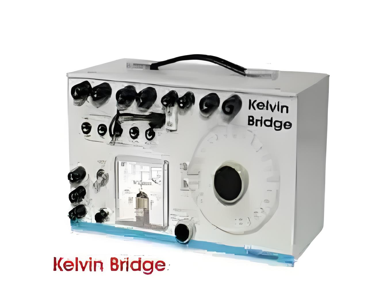
The resistance can be measured by a simple voltmeter ammeter method, Kelvin Bridge meter or automatic winding resistance measurement kit (ohm meter, preferably 25 Amps kit).


Caution for voltmeter ammeter method: Current shall not exceed 15% of the rated current of the winding. Large values may cause inaccuracy by heating the winding and thereby changing its temperature and resistance.


Note: The measurement of winding resistance of a transformer shall be carried out at each tap.


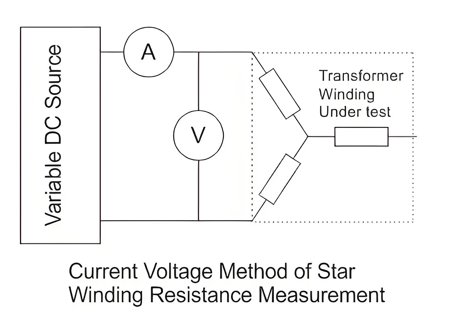
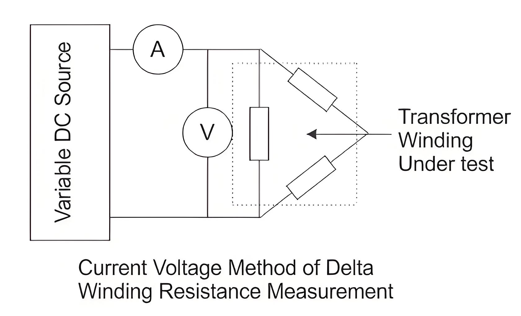
Current Voltage Method of Measurement of Winding Resistance


The transformer winding resistances can be measured by current voltage method. In this method of measurement of winding resistance, the test current is injected to the winding and corresponding voltage drop across the winding is measured. By applying simple Ohm’s law i.e. Rx = V ⁄ I, one can easily determine the value of resistance.


Procedure of Current Voltage Method of Measurement of Winding Resistance


  • Before measurement, the transformer should be off and without excitation for 3 to 4 hours. This allows the winding temperature to match the oil temperature.


  • Measurement is done with D.C.


  • To minimize observation errors, polarity of the core magnetization shall be kept constant during all resistance readings.


  • Voltmeter leads shall be independent of the current leads to protect it from high voltages which may occur during switching on and off the current circuit


  • The readings shall be taken after the current and voltage have reached steady state values. In some cases this may take several minutes depending upon the winding impedance.


  • The test current shall not exceed 15% of the rated current of the winding. Large values may cause inaccuracy by heating the winding and thereby changing its resistance.


  • For expressing resistance, the corresponding temperature of the winding at the time of measurement must be mentioned along with resistance value. As we said earlier that after remaining in switch off condition for 3 to 4 hours, the winding temperature would become equal to oil temperature. The oil temperature at the time of testing is taken as the average of top oil and bottom oil temperatures of transformer.


6a79f140457d1ddcd4b8b0eb98fdf28a.jpeg

  • For star connected three-phase winding, the resistance per phase would be half of the measured resistance between two line terminals of the transformer


  • For delta connected three-phase winding, the resistance per phase would be 0.67 times of measured resistance between two line terminals of the transformer.


  • This current voltage method of measurement of winding resistance of transformer should be repeated for each pair of line terminals of winding at every tap position.


b8ff38fb6e37b6b86ef37578d67893ba.jpeg


Bridge Method of Measurement of Winding Resistance


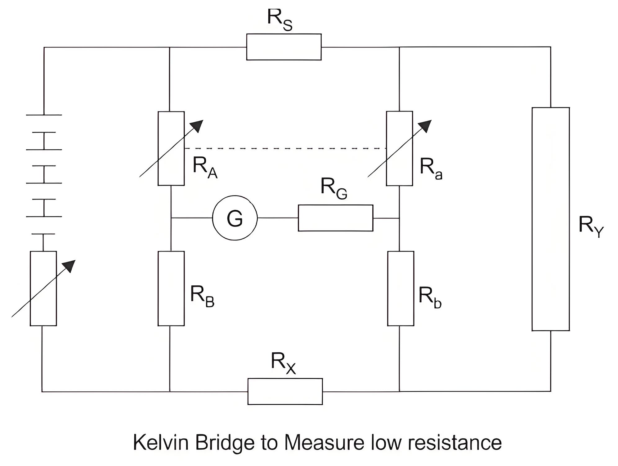
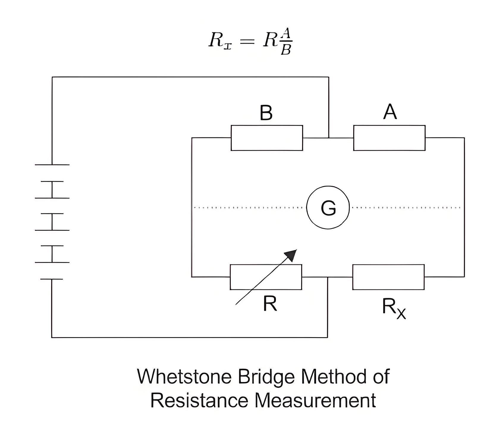
The main principle of the bridge method is based on comparing an unknown resistance with a known resistance. When currents flowing through the arms of the bridge circuit become balanced, the reading of galvanometer shows zero deflection that means at balanced condition no current will flow through the galvanometer.


A very small value of resistance (in milli-ohms range) can be accurately measured by the Kelvin bridge method whereas for higher value Wheatstone bridge method of resistance measurement is applied. In bridge method of measurement of winding resistance, the errors are minimized.


200599850ac781b2c8ed52488080e293.jpeg

255babd1174f5879d58d724b8e390655.jpeg


The resistance measured by Kelvin bridge


314e17193f20d82e8a9c3a9c831ea7cb.jpeg

All other steps to be taken during transformer winding resistance measurement in these methods are similar to that of current voltage method of measurement of winding resistance of transformer, except the measuring technique of resistance.


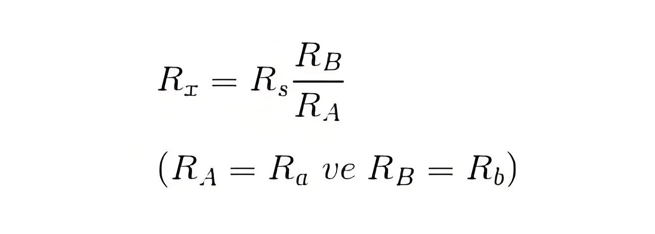
The resistance measured by Wheatstone bridge,


fef819b04665435cd6791860d3f2c22f.jpeg

Give a tip and encourage the author!
Recommended
SST Technology: Full-Scenario Analysis in Power Generation, Transmission, Distribution, and Consumption
I. Research BackgroundPower System Transformation NeedsChanges in energy structure are placing higher demands on power systems. Traditional power systems are transitioning toward new-generation power systems, with the core differences between them outlined as follows: Dimension Traditional Power System New-Type Power System Technical Foundation Form Mechanical Electromagnetic System Dominated by Synchronous Machines and Power Electronic Equipment Generation-Side Form M
Echo
10/28/2025
Rectifier vs Power Transformer: Key Differences
Differences Between Rectifier Transformers and Power TransformersRectifier transformers and power transformers both belong to the transformer family, but they differ fundamentally in application and functional characteristics. The transformers commonly seen on utility poles are typically power transformers, while those supplying electrolytic cells or electroplating equipment in factories are usually rectifier transformers. Understanding their differences requires examining three aspects: working
Echo
10/27/2025
SST Transformer Core Loss Calculation and Winding Optimization Guide
SST High-Frequency Isolated Transformer Core Design and Calculation Material Characteristics Impact:Core material exhibits varying loss behavior under different temperatures, frequencies, and flux densities. These characteristics form the foundation of overall core loss and require precise understanding of nonlinear properties. Stray Magnetic Field Interference:High-frequency stray magnetic fields around windings can induce additional core losses. If not properly managed, these parasitic losses
Dyson
10/27/2025
Design of a Four-Port Solid-State Transformer: Efficient Integration Solution for Microgrids
The use of power electronics in industry is increasing, ranging from small-scale applications such as chargers for batteries and LED drivers, to large-scale applications like photovoltaic (PV) systems and electric vehicles. Typically, a power system consists of three parts: power plants, transmission systems, and distribution systems. Traditionally, low-frequency transformers are used for two purposes: electrical isolation and voltage matching. However, 50-/60-Hz transformers are bulky and heavy
Dyson
10/27/2025
Related Products
Send inquiry
Download
Get the IEE Business Application
Use the IEE-Business app to find equipment, obtain solutions, connect with experts, and participate in industry collaboration anytime, anywhere—fully supporting the development of your power projects and business.