• Product
  • Suppliers
  • Manufacturers
  • Solutions
  • Free tools
  • Knowledges
  • Experts
  • Communities
Search


Digital Data of Control System

Encyclopedia
Encyclopedia
Field: Encyclopedia
0
China

Digital Data Definition


Digital data in control systems consists of discrete or sampled data that represents continuous signals in a digital format.


Sampling Process


Sampling is the conversion of analog signals to digital signals using a sampler, which switches ON and OFF.


The sampling process converts analog signals into digital signals using a switch, called a sampler, that turns ON and OFF. For an ideal sampler, the output pulse width is very small (almost zero). In discrete systems, Z transformations play a crucial role, similar to Fourier transform in continuous systems. Let’s explore Z transformations and their uses in detail.


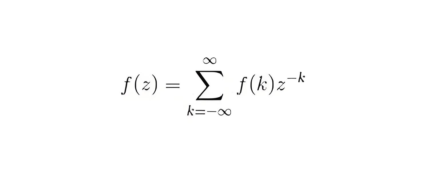
We define z transform as


Where, F(k) is a discrete data

Z is a complex number

F (z) is Fourier transform of f (k).


0a1e0386858964330c27353c80f75f3f.jpeg


Important Properties of z transformation are written below


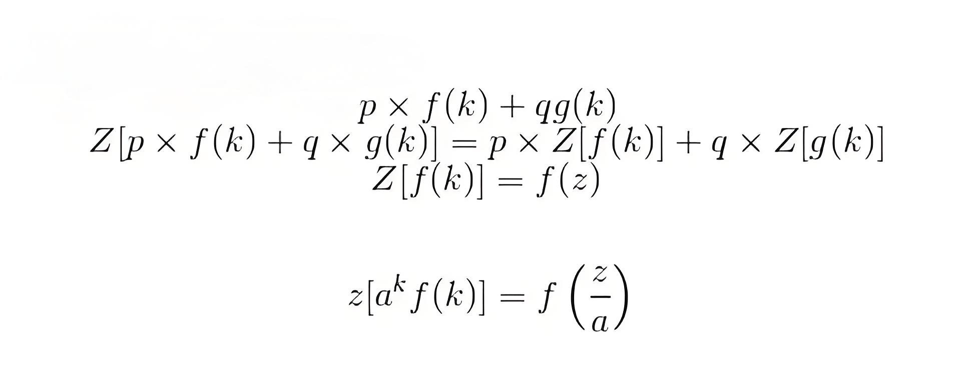
Linearity


Let us consider summation of two discrete functions f (k) and g (k) such that


such that p and q are constants, now on taking the Laplace transform we have by property of linearity:


Change of Scale: let us consider a function f(k), on taking the z transform we have


then we have by change of scale property


bed1b6bd060b422517c0f7e6c4daa32f.jpeg


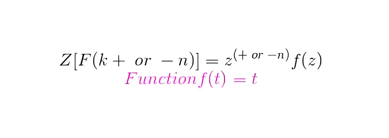
Shifting Property: As per this property


Now let us discuss some important z transforms and I will suggest readers to learn these transforms:


Laplace transformation of this function is 1/s 2 and the corresponding f(k) = kT. Now the z transformation of this function is


28d876cd31035b7a128c0366f5dc21f6.jpeg


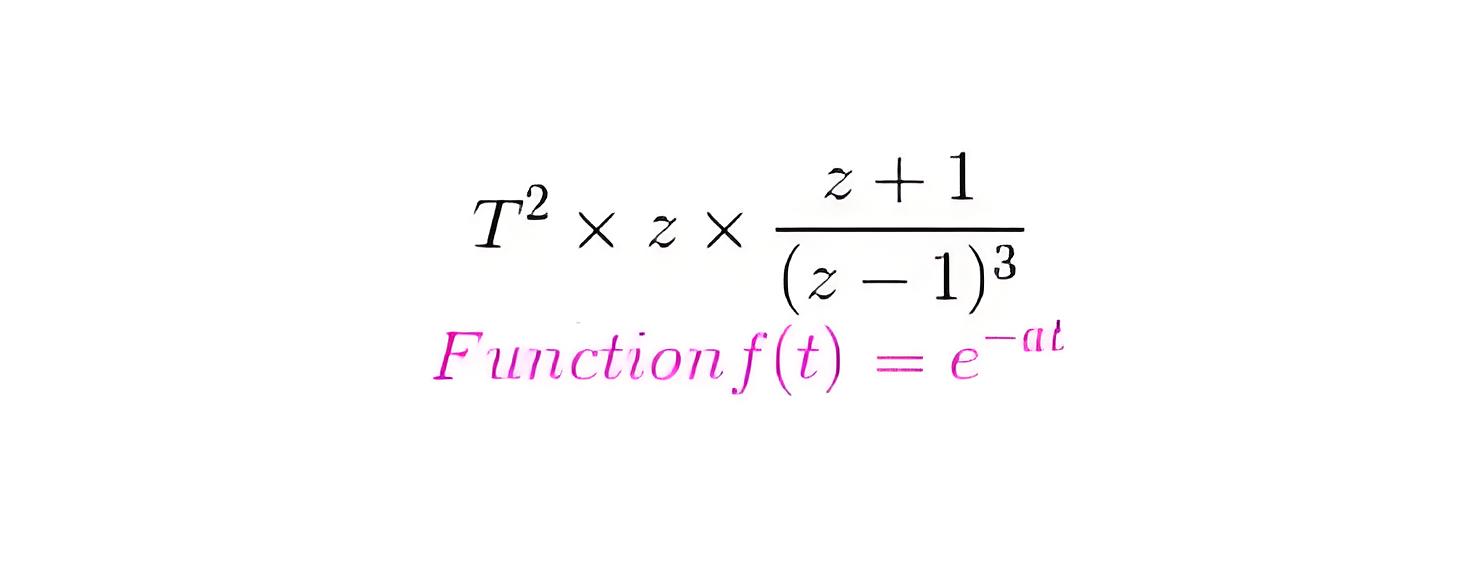
Laplace transformation of this function is 2/s3 and the corresponding f(k) = kT. Now the z transformation of this function is


Laplace transformation of this function is 1/(s + a) and the corresponding f(k) = e (-akT)


02419e0153bb9f6f9a42430e2313be7e.jpeg


Now the z transformation of this function is


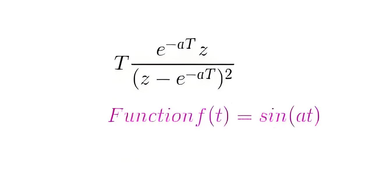
Laplace transformation of this function is 1/(s + a) 2 and the corresponding f(k) = Te-akT. Now the z transformation of this function is


0f3ac2ebb3cb3a2033a80f71b9a66a75.jpeg


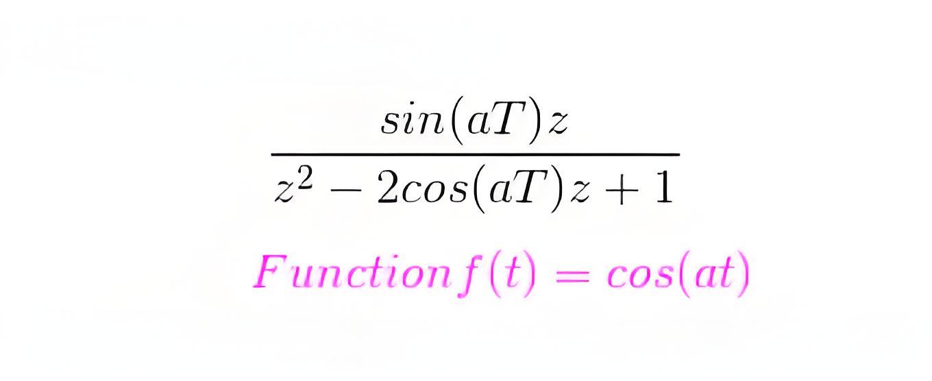
Laplace transformation of this function is a/(s 2 + a2) and the corresponding f(k) = sin(akT). Now the z transformation of this function is


645eb4b7b5305a9935435ee1a2c02dc8.jpeg 

Laplace transformation of this function is s/(s 2 + a2) and the corresponding f(k) = cos(akT). Now the z transformation of this function is


5ad9ceb3e4a165cbd74036853bd1f52a.jpeg


Now sometime there is a need to sample data again, which means converting discrete data into continuous form. We can convert digital data of control system into continuous form by hold circuits which are discussed below:


6df225009b2d9686157a20eba8dc560a.jpeg


Hold Circuits: These are the circuits which converts discrete data into continuous data or original data. Now there are two types of Hold circuits and they are explained in detail:


d070a50c1295d56763b9ccb2fdcc9d01.jpeg


Zero Order Hold Circuit


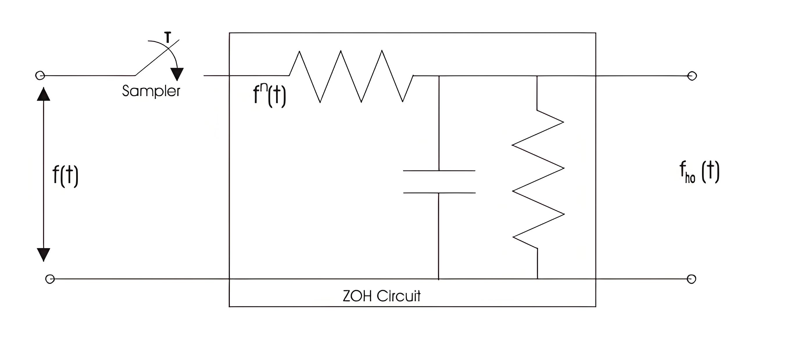
The block diagram representation of the zero order hold circuit is given below:


Figure related to zero order hold.


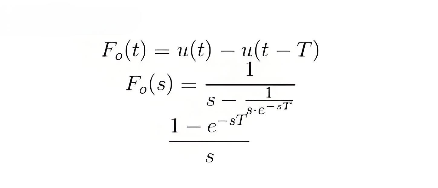
In the block diagram we have given an input f(t) to the circuit, when we allow input signal to pass through this circuit it reconverts the input signal into continuous one. The output of the zero order hold circuit is shown below.Now we are interested in finding out the transfer function of the zero order hold circuit. On writing the output equation we have


on taking the Laplace transform of the above equation we have


From the above equation we can calculate transfer function as


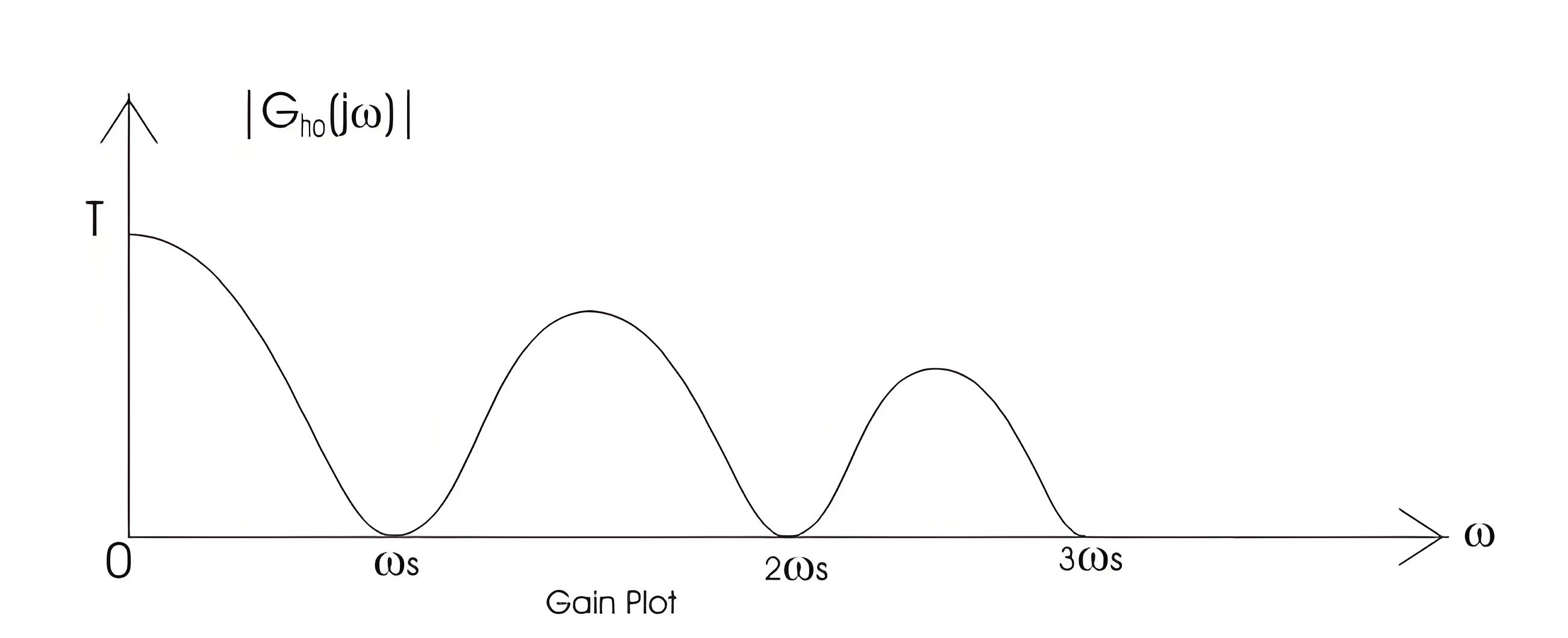
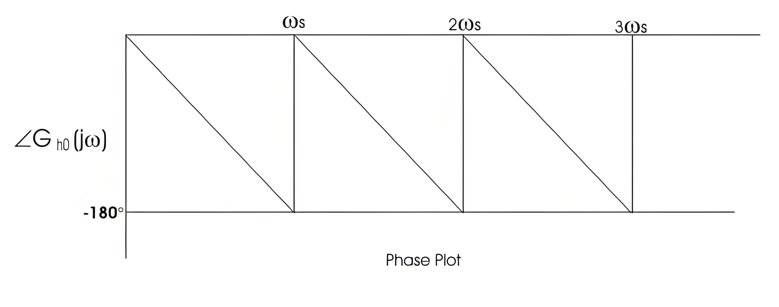
On substituting s=jω we can draw the bode plot for the zero order hold circuit. The electrical representation of the zero order hold circuit is shown below, which consists of a sampler connected in series with a resistor and this combination is connected with a parallel combination of resistor and capacitor.


82d9b95ea45a7beefba09102f61dee5e.jpeg


4f0c57162ab2b3168764981267f560fd.jpeg


GAIN PLOT – frequency response curve of ZOH


PHASE PLOT – frequency response curve of ZOH


94c6b68814e6ce572be54c71eaa4abb6.jpeg


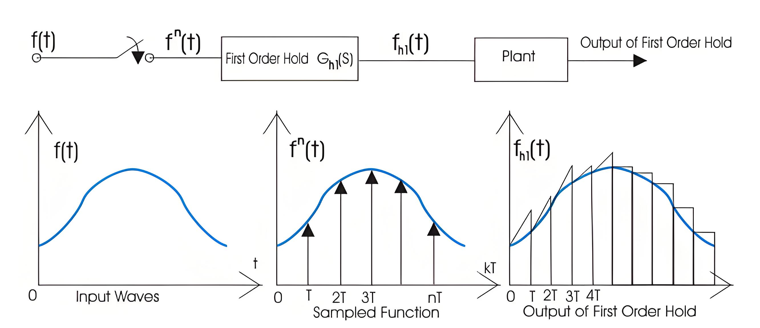
First Order Hold Circuit


The block diagram representation of the first order hold circuit is given below:


6d068747957f67af0f2c92f60b032440.jpeg


First Order Hold Circuit


In the block diagram we have given an input f(t) to the circuit, when we allow input signal to pass through this circuit it reconverts the input signal into continuous one. The output of the first order hold circuit is shown below: Now we are interested in finding out the transfer function of the first order hold circuit. On writing the output equation we have


On taking the Laplace transform of the above equation we have


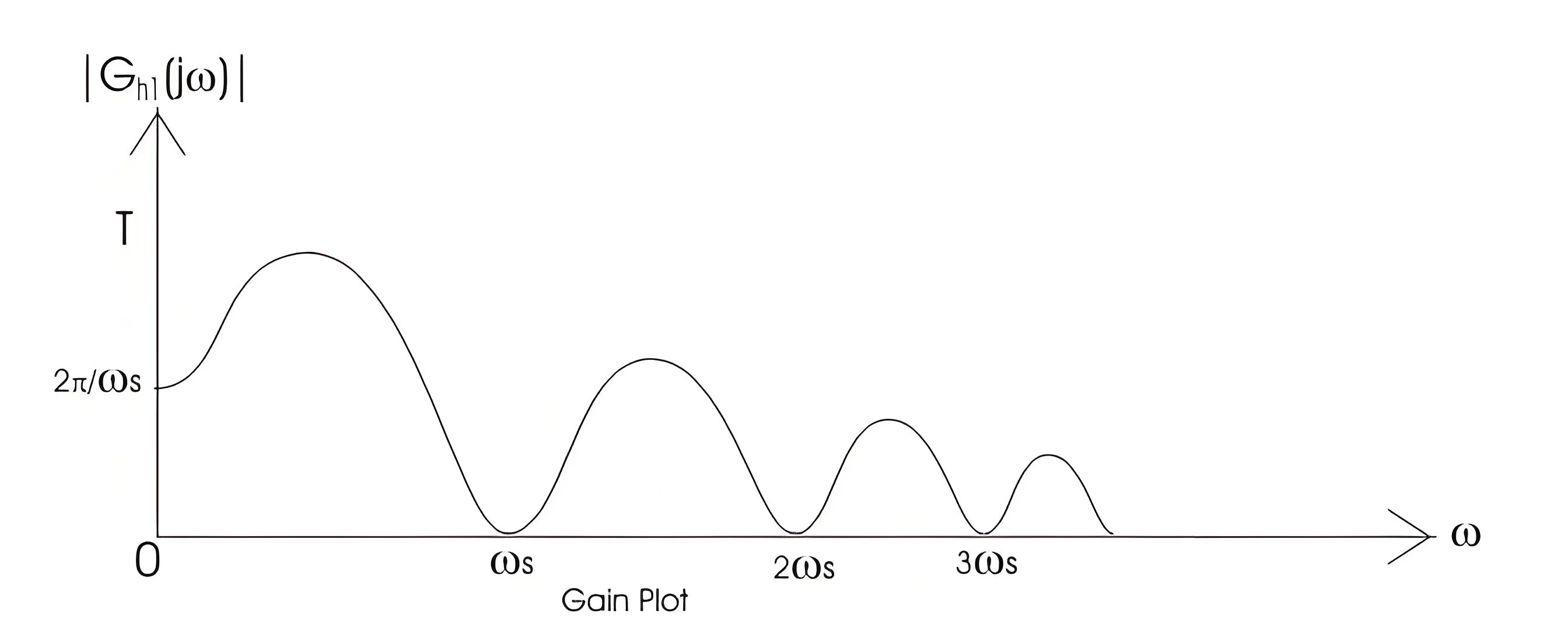
From the above equation we can calculate transfer function as (1-e -sT)/s. on substituting s=jω we can draw the bode plot for the zero order hold circuit.


The bode plot for the first order hold circuit is shown below which consists of a magnitude plot and a phase angle plot.The magnitude plot starts with magnitude value 2π/ωs.


c3547f4d1c2c672c274906d6ff3cb35d.jpeg


Give a tip and encourage the author!
Recommended
THD Measurement Error Standards for Power Systems
Error Tolerance of Total Harmonic Distortion (THD): A Comprehensive Analysis Based on Application Scenarios, Equipment Accuracy, and Industry StandardsThe acceptable error range for Total Harmonic Distortion (THD) must be evaluated based on specific application contexts, measurement equipment accuracy, and applicable industry standards. Below is a detailed analysis of key performance indicators in power systems, industrial equipment, and general measurement applications.1. Harmonic Error Standar
Edwiin
11/03/2025
How Vacuum Tech Replaces SF6 in Modern Ring Main Units
Ring main units (RMUs) are used in secondary power distribution, directly connecting to end-users such as residential communities, construction sites, commercial buildings, highways, etc.In a residential substation, the RMU introduces 12 kV medium voltage, which is then stepped down to 380 V low voltage through transformers. The low-voltage switchgear distributes electrical energy to various user units. For a 1250 kVA distribution transformer in a residential community, the medium-voltage ring m
James
11/03/2025
Why Monitoring Accuracy Matters in Power Quality Systems
The Critical Role of Monitoring Accuracy in Power Quality Online DevicesThe measurement accuracy of online power quality monitoring devices is the core of the power system’s “perception capability,” directly determining the safety, economy, stability, and reliability of power supply to users. Inadequate accuracy leads to misjudgment, incorrect control, and flawed decision-making—potentially causing equipment damage, economic losses, or even grid failures. Conversely, high accuracy enables precis
Oliver Watts
10/30/2025
How Does Power Dispatching Ensure Grid Stability and Efficiency?
Electric Power Dispatching in Modern Power SystemsThe power system is a critical infrastructure of modern society, providing essential electrical energy for industrial, commercial, and residential use. As the core of power system operation and management, electric power dispatching aims to meet electricity demand while ensuring grid stability and economic efficiency.1. Basic Principles of Electric Power DispatchingThe fundamental principle of power dispatching is to balance supply and demand by
Echo
10/30/2025
Send inquiry
Download
Get the IEE Business Application
Use the IEE-Business app to find equipment, obtain solutions, connect with experts, and participate in industry collaboration anytime, anywhere—fully supporting the development of your power projects and business.