Circuit Breaker Operation

Circuit Breaker Definition
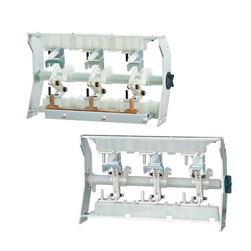
A circuit breaker is defined as a device that opens and closes electrical contacts to protect circuits from faults.
Therefore, circuit breakers must operate reliably without any delay. To ensure this reliability, the operating mechanism is more complex than it first appears. The distance and speed of the moving contacts during opening and closing are crucial design parameters for circuit breakers.
Contact gap, traveling distance of moving contacts and their velocity are determined by types of arc quenching medium, current and voltage rating of a circuit breaker.The typical operation of a circuit breaker is shown in a characteristic curve graph.
Here in the graph, X axis represents time in milli seconds and y axis represents distance in milli meter.
Let’s at time, T0 current starts flowing through the closing coil. After time T1 the moving contact starts traveling towards fixed contact. At time T2 moving contact touches fixed contact. At time T3 the moving contact reaches at its close position. T3 – T2 is overloading period of these two contacts (moving and fixed contact). After time T3 the moving contact bounce back little bit and then again comes to its fixed closed position, after time T4.

Now we come to the tripping operation. Let’s at time T5 current starts flowing through trip coil of the circuit breaker. At time T6 moving contact starts traveling backward for opening the contacts. After time T7, the moving contact finally detaches the fixed contact. Time (T7 – T6) is over lapping period.
Now at time T8 the moving contact comes back to its final open position but here it will not be at rest position since there will be some mechanical oscillation of moving contact before coming to its final rest position. At time T9 the moving contact finally comes to its rest position. This holds true for both standard and remote control circuit breaker.
Circuit Breaker Opening Operation Requirement
A circuit breaker should open quickly to limit contact erosion and interrupt faulty current promptly. However, the travel distance of the moving contact is also determined by the need to maintain a sufficient contact gap to withstand normal dielectric stresses and lightning impulse voltage when the breaker is open.
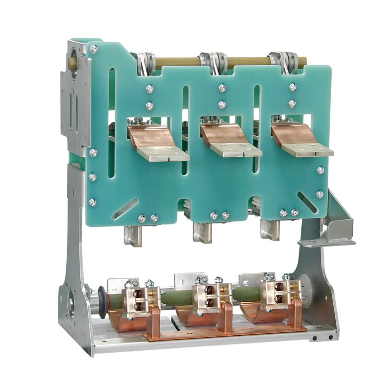
The need for carrying the continuous current and for withstanding a period of arc in circuit breaker, makes it necessary to use two sets of contacts in parallel one the primary contact which is always made of high conductive materials such as copper and the other is arcing contact, made of arc resistance materials such as tungsten or molybdenum, which has much lower conductivity than primary contacts.
During opening circuit breaker operation, the primary contacts open before the arcing contacts. However, due to the difference in the electrical resistance and the inductor of the electrical paths of the primary and arcing contacts, a finite time is required to attain total current commutation, i.e. from primary or main contacts to arcing contact branch.
So when the moving contact starts traveling from closed position to open position the contact gap gradually increases and after some time a critical contact position reaches which indicates the minimum conduct gap required for preventing re-arcing after very next current zero.
The remaining part of the travel is required only for maintaining sufficient dielectric strength between contacts gap and for deceleration purpose.
Circuit Breaker Closing Operation Requirement
During closing operation of circuit breaker the followings are required,
The moving contact must travel towards fixed contact at sufficient speed to prevent pre-arcing phenomenon. As the contact gap reduces, arcing may start before contacts are closed finally.
During closing of contacts, the medium between contacts is replaced, hence sufficient mechanical power to be supplied during this circuit breaker operation to compress dielectric medium in the arcing chamber.
After hitting fixed contact, the moving contact may bounce back, due to repulsive force which is not at all desirable. Hence sufficient mechanical energy is to be supplied to overcome repulsive force due to closing operation on fault.
In spring-spring mechanism, generally tripping or opening spring is charged during closing operation. Hence sufficient mechanical energy also to be supplied to charge the opening spring.