• Product
  • Suppliers
  • Manufacturers
  • Solutions
  • Free tools
  • Knowledges
  • Experts
  • Communities
Search


Arc Suppression Coil or Petersen Coil

Encyclopedia
Encyclopedia
Field: Encyclopedia
0
China

Arc Suppression Coil Definition


An arc suppression coil, also known as a Petersen coil, is an inductive coil used to neutralize the capacitive charging current in underground power networks during an earth fault.


Purpose and Function


The coil reduces the large capacitive charging current during an earth fault by creating an opposite inductive current.


Working Principle


The inductive current generated by the coil cancels out the capacitive current, preventing arcing at the fault point.


Capacitive Current in Underground Systems


Underground cables have a continuous capacitive current due to the dielectric insulation between the conductor and the earth.


Inductance Calculation


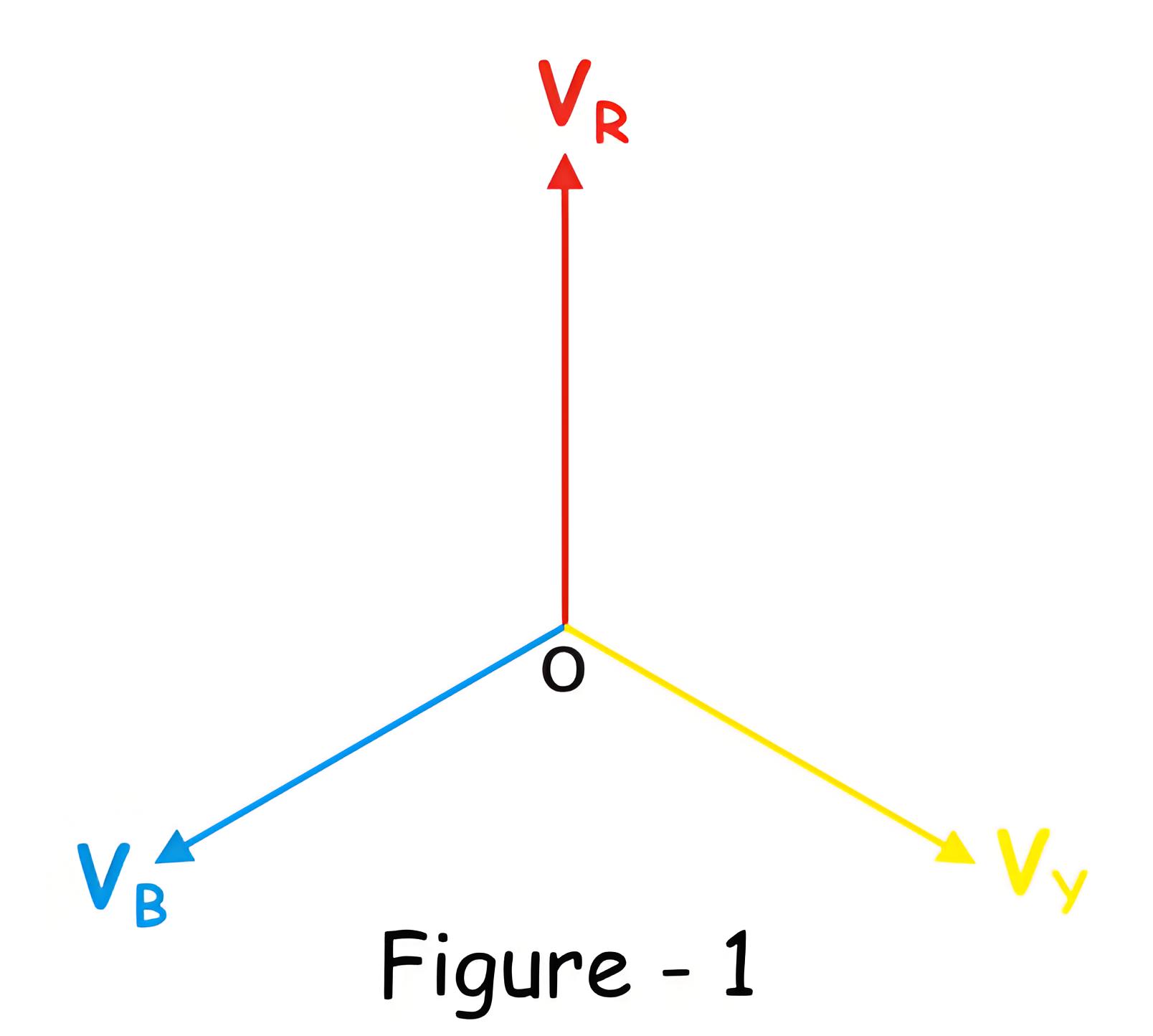
The voltages of a three phase balanced system is shown in figure – 1.


In underground high voltage and medium voltage cable networks, each phase has capacitance between the conductor and the earth, leading to a continuous capacitive current. This current leads the phase voltage by 90 degrees as shown in figure – 2.


2c625f51e0b220920728e226a9a14a3d.jpeg

a6ccb9896da0ce6e866a9141547d580d.jpeg


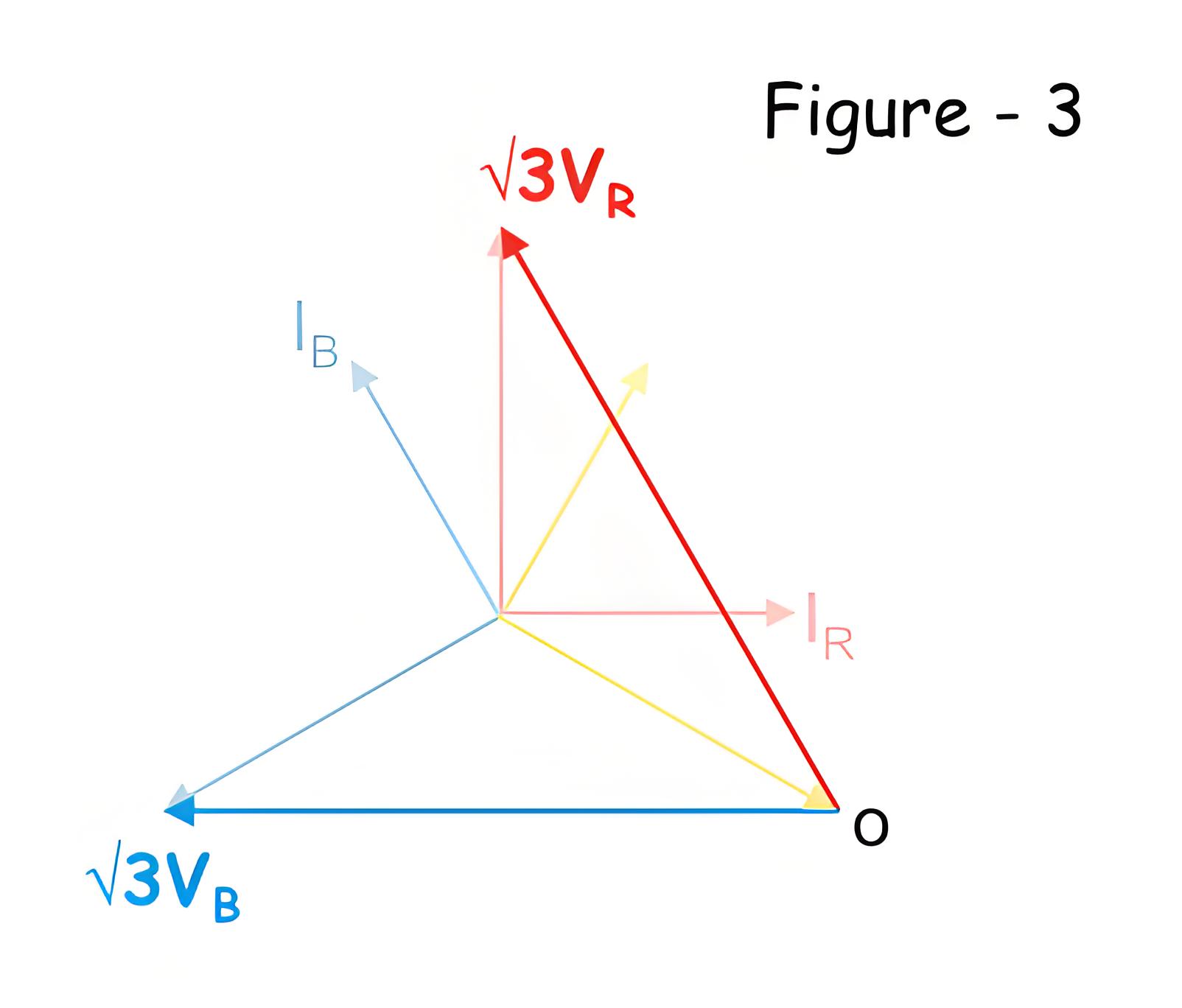
If an earth fault occurs in the yellow phase, the voltage of the yellow phase to ground becomes zero. The system’s neutral point shifts to the tip of the yellow phase vector. Consequently, the voltage in the healthy phases (red and blue) increases to &sqrt;3 times the original value.


a6ccb9896da0ce6e866a9141547d580d.jpeg


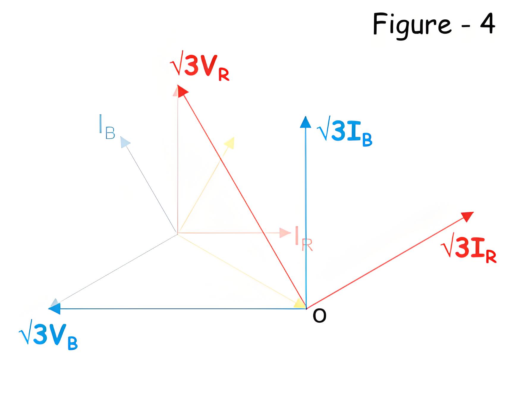
Naturally, the corresponding capacitive current in each healthy phase (red and blue) becomes &sqrt;3 of the original as shown in figure-4, below.


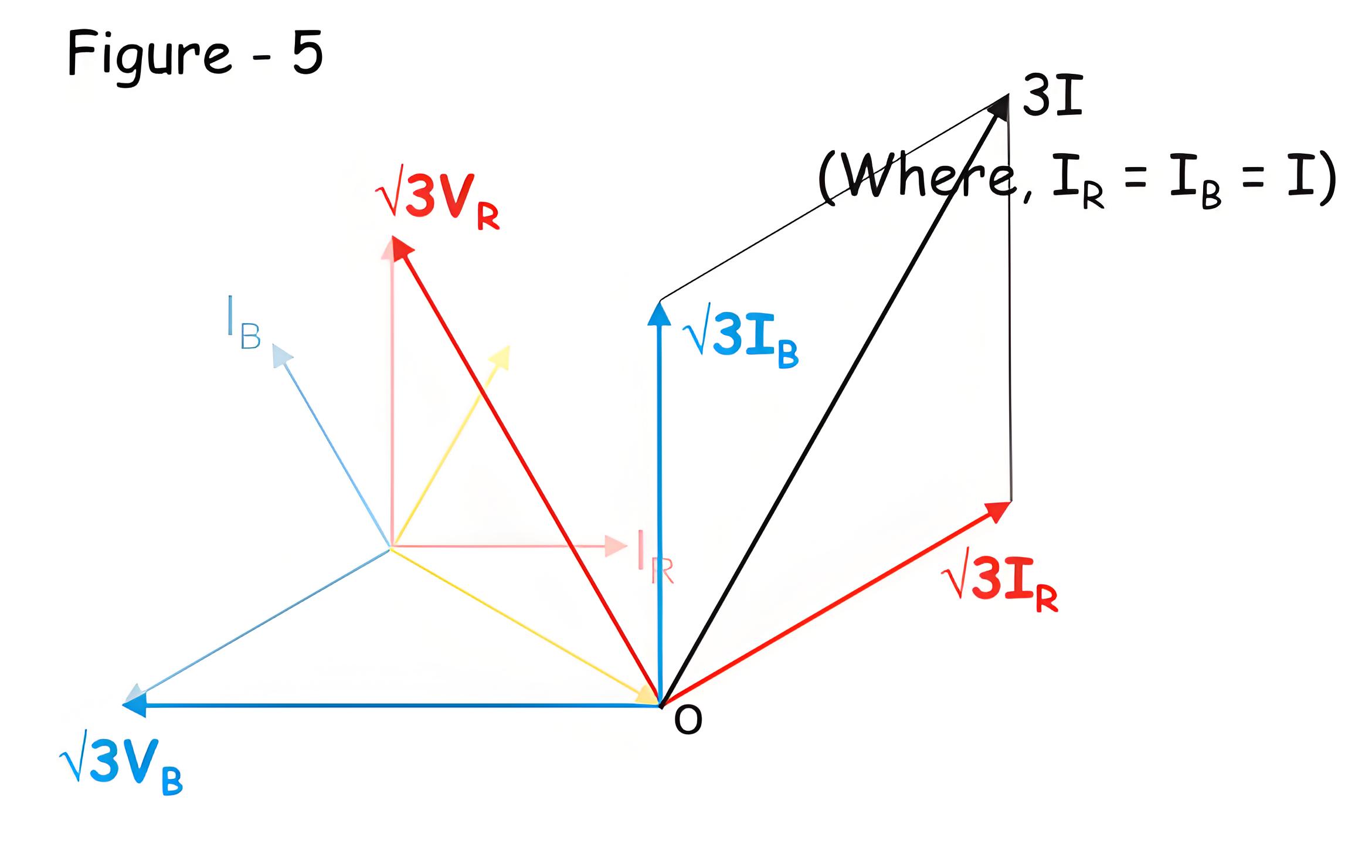
The vector sum that is resultant of these two capacitive current now will be 3I, where I is taken as rated capacitive current per phase in the balanced system. That means, at healthy balanced condition of the system, I R = IY =IB = I.


496665dfb04f5a88f973e1b0b79fd896.jpeg


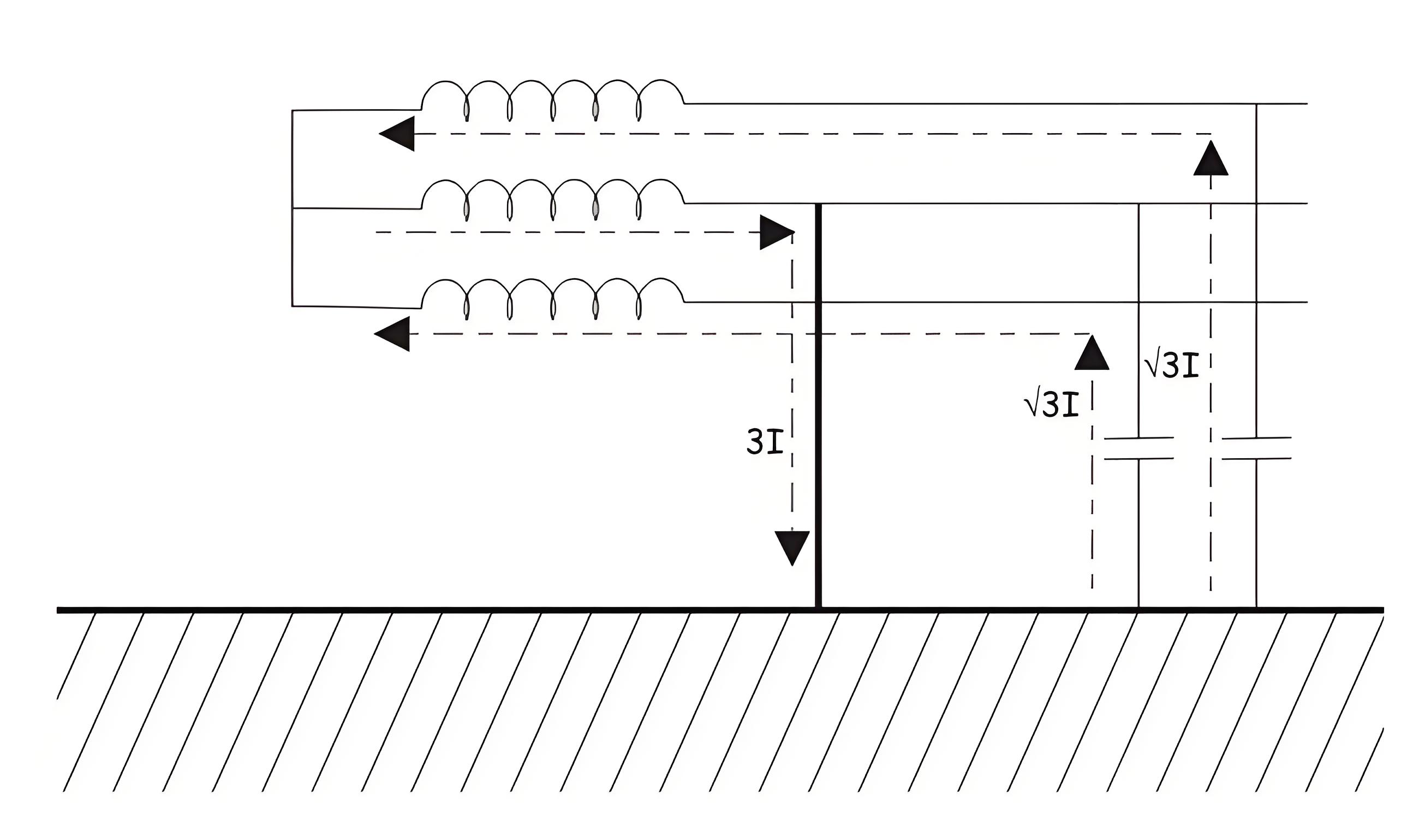
This is illustrated in the figure- 5 below,


This resultant current then flows through the faulty path to the earth as shown below.


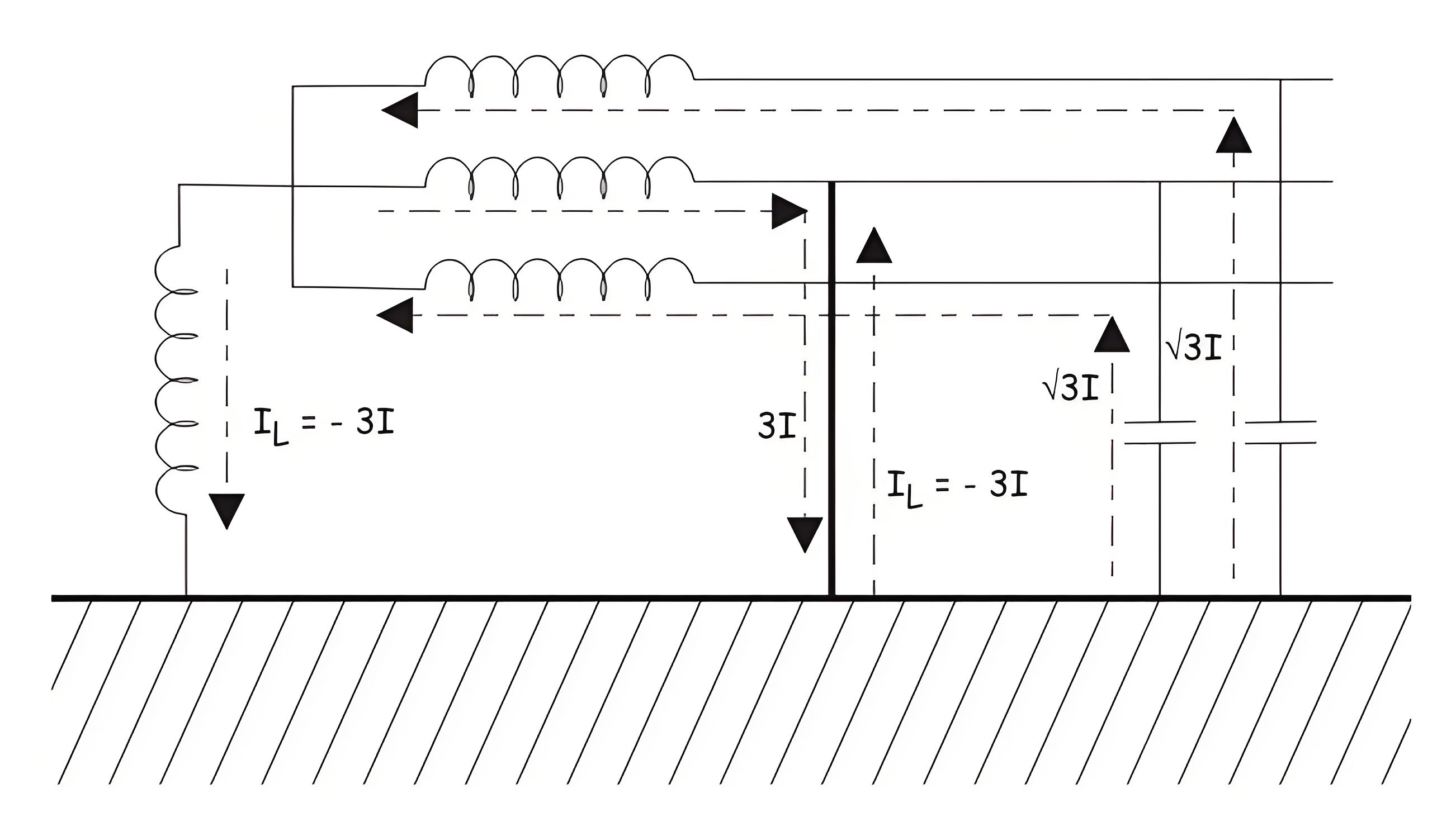
Now, if we connect one inductive coil of suitable inductance value (generally iron core inductor is used) between star point or neutral point of the system and ground, the scenario will be entirely changed. At faulty condition, the current through the inductor just equal and opposite in magnitude and phase of that of capacitive current through the faulty path. The inductive current also follow the faulty path of the system. The capacitive and inductive current cancels each other at the faulty path, hence there will not be any resultant current through the faulty path created due to capacitive action of the underground cable. The ideal situation is illustrated in the figure below.


This concept was first implemented by W. Petersen in 1917, that why the inductor coil is used for the purpose, called Petersen Coil.


dc14df4d10a6332e2daba580133d8d4d.jpeg

663b55f33b2a661d7044d160bf991cfc.jpeg

0660e51009e91fefb60efc9d1dbf1352.jpeg


The capacitive component of the fault current is high in the underground cabling system. When earth fault occurs, the magnitude of this capacitive current through the faulty path becomes 3 times more than rated phase to earth capacitive current of healthy phase. This causes significant shifting of zero crossing of current away from zero crossing of voltage in the system. Due to presence of this high capacitive current in the earth fault path there will be a series of re-striking at fault location. This may lead unwanted over voltage in the system.


The inductance of the Petersen Coil is selected or adjusted at such value which causes the inductive current which can exactly neutralize the capacitive current.

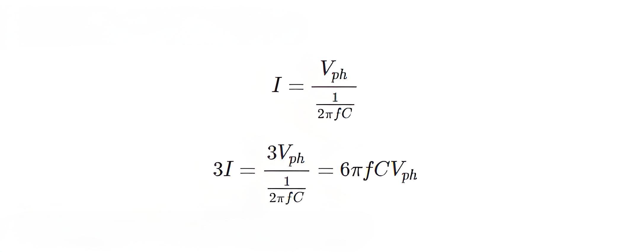
Let us calculate the inductance of Petersen Coil for a 3 phase underground system.For that let us consider capacitance between conductor and earth in each phase of a system, is C farad. Then the capacitive leakage current or charging current in each phase will be


So, the capacitive current through the faulty path during single phase to earth fault is


After fault, the star point will have phase voltage as the null point is shifted to fault point. So the voltage appears across the inductor is Vph. Hence, the inductive current through the coil is


4a0132db7deae91e16e7a181f2daa916.jpeg


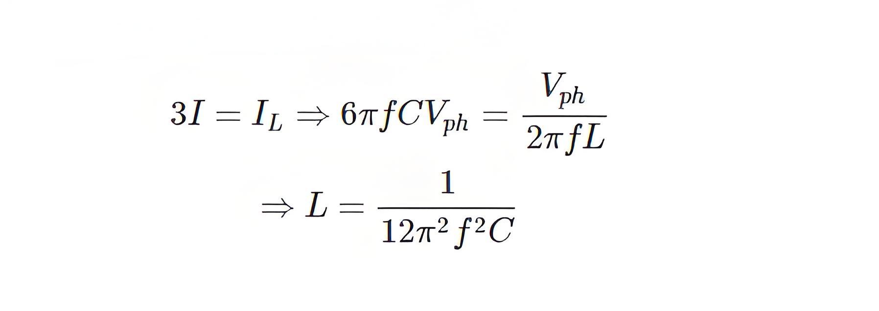
Now, for cancellation capacitive current of value 3I, IL must have same magnitude but 180o electrically apart. Therefore,


8a96d717cfdbcbbaf699ee75a76b8e97.jpeg


When the design or configuration of the system changes, such as length, cross-section, thickness, or insulation quality, the inductance of the coil must be adjusted. Therefore, Petersen coils often have a tap-changing arrangement.


b389513abf0c0cfc782caeb2e52b4b13.jpeg


Give a tip and encourage the author!
Recommended
What are the safety precautions and guidelines for using AC load banks?
AC load banks are electrical devices used to simulate real-world loads and are widely applied in power systems, communication systems, automation control systems, and other fields. To ensure personal and equipment safety during use, the following safety precautions and guidelines must be observed:Select an appropriate AC load bank: Choose an AC load bank that meets actual requirements, ensuring its capacity, voltage rating, and other parameters satisfy the intended application. Additionally, sel
Echo
11/06/2025
What should be noted when installing a Type K thermocouple?
Installation precautions for Type K thermocouples are critical to ensuring measurement accuracy and extending service life. Below is an introduction to the installation guidelines for Type K thermocouples, compiled from highly authoritative sources:1.Selection and Inspection Select the appropriate thermocouple type: Choose the right thermocouple based on the temperature range, medium properties, and required accuracy of the measurement environment. Type K thermocouples are suitable for temperatu
James
11/06/2025
 Causes and Preventive Measures of Fire and Explosion in Oil Circuit Breakers
Causes and Preventive Measures of Fire and Explosion in Oil Circuit Breakers
Causes of Fire and Explosion in Oil Circuit Breakers When the oil level in an oil circuit breaker is too low, the oil layer covering the contacts becomes too thin. Under the effect of the electric arc, the oil decomposes and releases flammable gases. These gases accumulate in the space beneath the top cover, mixing with air to form an explosive mixture, which can ignite or explode under high temperature. If the oil level inside the tank is too high, the released gases have limited space to expan
Felix Spark
11/06/2025
THD Measurement Error Standards for Power Systems
Error Tolerance of Total Harmonic Distortion (THD): A Comprehensive Analysis Based on Application Scenarios, Equipment Accuracy, and Industry StandardsThe acceptable error range for Total Harmonic Distortion (THD) must be evaluated based on specific application contexts, measurement equipment accuracy, and applicable industry standards. Below is a detailed analysis of key performance indicators in power systems, industrial equipment, and general measurement applications.1. Harmonic Error Standar
Edwiin
11/03/2025
Send inquiry
Download
Get the IEE Business Application
Use the IEE-Business app to find equipment, obtain solutions, connect with experts, and participate in industry collaboration anytime, anywhere—fully supporting the development of your power projects and business.