Fault Analysis and Improvement Measures for Light Gas Alarms in 25 MVA Arc Furnace Transformer

A 25 MVA electric arc furnace transformer at a certain company is an equipment imported from the former Soviet Union. It consists of three single-phase transformers, each rated at 8.333 MVA, with a connection group of D,d0. The primary voltage is 10 kV, and the secondary voltage ranges from 140 to 230.4 V. The tap-changing method is on-load tap changing with 21 steps (steps 11, 12, and 13 are combined as one step, totaling 23 positions). Each phase can be regulated independently, allowing separate adjustment of phases A, B, and C during smelting to maintain balanced current across the three-phase electrodes.
During normal operation, the B-phase transformer experienced two instances of light gas alarms. After gas release, power was restored and operation returned to normal. Oil samples were taken simultaneously for gas chromatographic analysis, and the results showed no abnormalities. At that time, the issue was primarily attributed to air ingress due to leakage in the negative-pressure section of the oil piping system. However, in the following days, light gas alarms occurred frequently, reaching up to 6–7 times per shift. Subsequent oil sampling and gas chromatographic analysis revealed abnormal results.
1. Analysis of the Light Gas Fault in the Arc Furnace Transformer
Gas chromatographic analysis is based on gases dissolving in oil; when the concentration exceeds the oil's solubility limit, free gas forms. The composition of these gases (in μL/L) is closely related to the type and severity of internal faults. Therefore, this method can detect internal transformer faults at an early stage and continuously monitor the location and development of such faults.
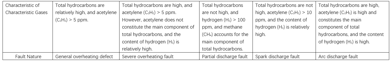
Analysis conclusion: Total hydrocarbons and acetylene levels have exceeded acceptable limits. According to the three-ratio method coding rules, the code combination is 1-0-1, indicating the fault type is arc discharge.

2. Core Lifting Inspection Findings and Analysis
2.1 Core Lifting Inspection Findings
To promptly eliminate equipment hidden dangers and prevent fault escalation, a core lifting inspection was performed. The inspection revealed that the fault originated in the polarity switch contacts inside the on-load tap changer, which showed severe overheating and significant burn damage.
2.2 Analysis of Overheating and Damage to Polarity Switch Contacts
2.2.1 Long-term Overload Current on Contacts
The rated current through the polarity switch contact was calculated to be 536 A. Due to frequent overload operation of the furnace, the actual current exceeded the switch's rated capacity, causing excessive temperature rise at the contact. This overheating formed localized hot spots, increasing contact resistance and initiating a "vicious cycle" that led to oil decomposition, generation of free gas, and subsequent light gas alarms.
2.2.2 Long-term Operation of Polarity Switch Contacts at the Same Position
The polarity switch is essentially a selector switch with two positions: one for voltage taps 1–10 and the other for taps 11–23. In actual operation, the furnace's secondary voltage was consistently operated at taps 21–23, causing the switch contacts to remain in one position for extended periods. This eliminated normal wiping action, preventing self-cleaning of the contact surface. Organic contaminants accumulated, forming a stable, dark insulating film. This film progressively reduced current-carrying capacity, increased contact resistance, and raised contact temperature. The elevated temperature further accelerated contaminant deposition, reinforcing the "vicious cycle" and resulting in free gas generation and gas alarms.
3 Improvement Measures
3.1 Increase Contact Current-Carrying Capacity and Reduce Contact Resistance
To address frequent furnace overloads and meet production demands, the polarity switch contacts were remanufactured. Based on actual measurements and without altering installation dimensions, the width of the original linear contact surface was increased by 2 mm to enhance current capacity. The original chromium-nickel alloy plating was replaced with hard silver plating, and the plating thickness was increased by 0.5 mm. This improved contact pressure, reduced contact resistance, and enhanced conductivity.
3.2 Regular No-Load Operation of the Polarity Switch
To prevent prolonged stationary operation and associated resistance increase, additional no-load operations of the polarity switch were included during transformer preventive testing. Users were also required to perform a no-load operation of the switch once per month. The purpose is to mechanically wipe and clean the contact surface, removing deposits and reducing contact resistance.
4 Conclusion
Overheating faults in transformer tap changer contacts are among the major issues affecting stable operation. Timely and accurate identification of fault nature and location is essential for targeted corrective actions. Lessons learned should be continuously accumulated to improve analytical accuracy. For the light gas alarms in the arc furnace transformer, root causes were identified through comprehensive analysis, and effective measures were implemented to eliminate the hidden danger. After more than two years of operation, no similar abnormalities have occurred. This solution prevented economic losses associated with transformer removal, repair, and unplanned downtime, achieving significant economic benefits.
Recommended