• Product
  • Suppliers
  • Manufacturers
  • Solutions
  • Free tools
  • Knowledges
  • Experts
  • Communities
Search


Operation Method for PT Resonance in 500kV GIS Switching Station

James
Field: Electrical Operations
China

1. Causes of Resonance

A 500kV GIS switching station is designed following the principle of “primary equipment intelligence and secondary equipment networking”. The PT high - voltage side has no disconnector and is directly connected to the bus GIS. Through the analysis of fault recording diagrams, when the 5021 circuit breaker opens, the fracture capacitance and PT form a series circuit. Moreover, the bus voltage, after being paralleled by the PT inductance, shows inductive characteristics. The capacitance is disturbed, triggering resonance.

The saturated current lasts for more than 1 hour and 40 minutes, causing PT heating and damage risk. The equivalent circuit includes power supply voltage (Es), circuit breaker (CB), fracture grading capacitor (Cs), bus - to - ground capacitor (Ce), and PT primary coil resistance and inductance (Re, Lcu).

To investigate the cause, the second line was de - energized. The detection of PT insulation resistance, DC resistance, and SF₆ gas pressure showed no abnormalities. Since the electromagnetic PT is a nonlinear inductor with an iron core and GIS equipment components have capacitance, under specific scenarios, the LC series circuit meets the resonance conditions, causing continuous resonance.

2. Scientific Suppression Solutions
2.1 Solution Proposal

PT resonance is common in 500kV GIS switching stations. The permeability of ferromagnetic materials changes with the external magnetic field: as the magnetic field increases → the magnetic induction intensity rises. After saturation, the permeability reaches a peak value. With further increase, the permeability decreases. According to the coil induction formula:

(N is the number of turns, μ is the permeability, S is the equivalent cross - sectional area of the magnetic circuit, and lm is the equivalent magnetic circuit length), the coil turns and magnetic circuit parameters of the electromagnetic PT are constant, and the inductance has a linear relationship with the permeability; when the iron core is saturated, the permeability drops sharply, the inductance becomes smaller, showing nonlinear characteristics. If a low - frequency voltage appears in the circuit, the PT iron core is saturated, the equivalent inductance decreases, and the winding excitation current surges by hundreds of times, causing resonance heating.

For resonance, the following solutions are proposed:

  • Change the power - on/off sequence: When de - energizing the bus, turn off the PT first, then the bus; when energizing, charge the bus first, then put the PT into operation. This can disrupt the resonance conditions but requires adjusting the operation sequence and the PT needs to be equipped with a disconnector.

  • Remove circuit breaker fracture capacitance: It can eliminate resonance conditions but will reduce the circuit breaker interrupting capacity.

  • Connect damping resistance: Considering the actual situation, connect a damping resistance to the remaining cable set of the bus PT to suppress resonance overvoltage and overcurrent.

2.2 Accident Handling

The incoming - line PT of a 500kV GIS switching station had repeated resonance during de - energization, damaging the PT and affecting equipment operation. During the incoming - line de - energization operation (switching to hot standby → cold standby, etc.), the PT still resonated. Therefore, PT parameters were calculated, the number of primary/secondary winding turns was adjusted to reduce the magnetic flux density and change the inductance; an anti - resonance coil was installed, and the new PT and incoming - line PT were replaced. After observation and statistics, no resonance occurred in the switching station, and the equipment operated normally.

3. Preventive Measure: Install Automatic Resonance Elimination Equipment

When the bus PT is directly connected to the GIS bus, the PT and bus - to - ground resistances are not considered. Let the PT inductance be L and the bus - to - ground capacitance be C; the two are paralleled to form an impedance Z, and the calculation formula is

By installing automatic resonance elimination equipment, resonance can be suppressed based on impedance characteristics.

To reduce PT resonance impacts on 500kV GIS incoming - line PTs, air switches and nonlinear resistors are added to PT residual voltage windings (via coordination with manufacturers during full shutdowns) for automatic resonance elimination. An emergency plan for no - load bus resonance failure is required.

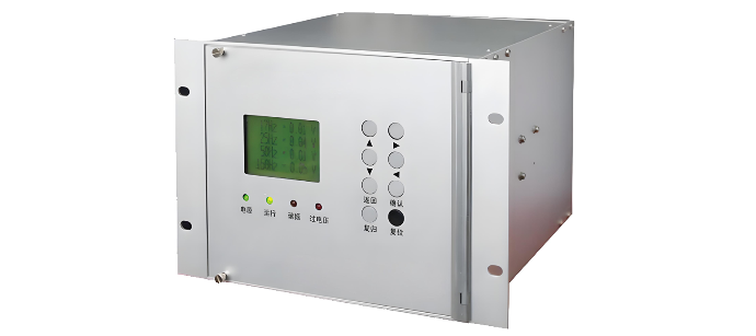
500kV GIS busbars use open - type installation; other devices are SF₆ - insulated (small footprint, high reliability, 20 - year+ maintenance intervals, as used in the Three Gorges Project). Reliable automatic resonance eliminators (e.g., LXQ - type with SiC, compact and easy to install; WXZ196 microcomputer - based, high - integration for real - time harmonic elimination) can prevent resonance.

3.2 Operating Regulation Improvements

For 500kV GIS operation:

  • Pre - analysis: Identify PT resonance risks; clarify roles for power/NCS operators.

  • Device control: Before shutting down the last circuit breaker, separate the bus. Close K1/K2 in the PT box; at the station entrance, activate the bus resonance eliminator (close K3, prepare resistors).

  • Real - time monitoring: NCS tracks circuit breakers and bus voltages. Zero voltage = no resonance; fluctuating voltage = resonance detected.

  • Response: For resonance, close K3 to engage resistors. If ineffective, open circuit breaker disconnectors for manual elimination.

4. Summary

During 500kV GIS design, simulate bus PT resonance to select robust PTs (prevent core saturation during switching). For existing resonance, take targeted actions (e.g., bus/PT replacement) to ensure safe operation. This “prevention - operation - design” system enhances anti - resonance capabilities.

Give a tip and encourage the author!
Recommended
Mismatched AC Contactor Sizing? These 4 Typical Issues You Must Not Ignore – Click to View Solutions
AC contactors (with the electrical schematic code KM) are core electrical devices used to control the connection/disconnection between power supplies and loads in circuits, and they are also common equipment that electricians need to work with regularly. In practice, it is not uncommon to find that some peers make mistakes in selecting AC contactors, leading to improper sizing and subsequent persistent issues. Here, four of the most typical common mistakes are highlighted for reference.I. Over-R
James
09/11/2025
Proper Installation of AC Contactors | A Practical Guide to Avoid Burning and Misoperation, Master It in One Article
AC contactors are widely used for switching and controlling power circuits. They use main contacts to open and close circuits, and auxiliary contacts to execute control commands. Main contacts typically only have normally open contacts, while auxiliary contacts often have two pairs of contacts with normally open and normally closed functions. Small-sized contactors are also frequently used as intermediate relays to work with main circuits, thereby achieving the function of remote control or cont
James
09/11/2025
Technical Analysis of 220 kV High-Voltage Cable Construction in Winter
1.Work Environment Requirements and Safeguard MeasuresBased on technical requirements for cable equipment storage, laying, transportation, laying, transposition, testing, and cable terminations, the project owner and construction units have conducted extensive trials and implemented protective measures regarding ambient temperature, humidity, bending radius, traction control, and route optimization. These measures ensure high-voltage cable quality and on-site safety under harsh winter conditions
James
09/03/2025
Considerations and Recommendations for Flame-Retardant Selection of High-Voltage Cables
1.Flame-Retardant Cable Classification StandardsThe flame-retardant standard system is divided into two main categories. The first category follows the "Classification of Burning Behavior for Electric and Optical Fiber Cables" GB 31247. Cables complying with this standard system are widely used in densely populated areas such as high-speed railways and subways. This standard imposes strict requirements on parameters such as smoke density, heat release, and total smoke production, and cables typi
James
09/03/2025
Seed Inquiry
Download
Get the IEE Business Application
Use the IEE-Business app to find equipment, obtain solutions, connect with experts, and participate in industry collaboration anytime, anywhere—fully supporting the development of your power projects and business.