When two parts of an electrical network with the same operating voltage are coupled, a phase displacement switching phenomenon occurs if their equivalent sources have different phase angles, with some or all phases being 180° out of phase. During the switching operation, the circuit breaker encounters source voltages with differing phase angles, leading to the presence of phase-displaced currents in the connection. These currents must be reliably interrupted by the circuit breakers on both sides of the connection.
Specifically, the phase angle difference between the rotating vectors representing the source voltages results in out-of-sync instantaneous voltage waveforms, causing significant transient currents and voltage stresses at the moment of switching. For transient recovery voltage (TRV), this switching task is characterized by active power sources on both sides of the circuit breaker, increasing the complexity and challenges of the switching operation.
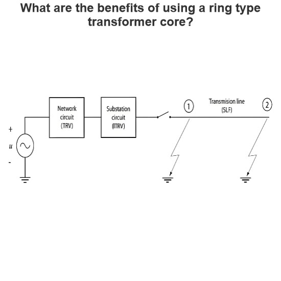
As shown in Figure 1, assume that power sources S1 and S2 represent two sources with different phase angles. When the circuit breaker switches between these two sources, the phase angle difference can lead to a substantial increase in transient current, imposing greater breaking demands on the circuit breaker. Therefore, the circuit breaker must have sufficient capability to handle these high-stress conditions, ensuring safe and reliable switching operations.
Key Points Summary
Phase Displacement Switching: Occurs when switching between two sources with different phase angles.
Transient Currents: Significant transient currents are generated due to phase angle differences.
Transient Recovery Voltage (TRV): The switching task involves active power sources on both sides of the circuit breaker, increasing complexity.
Circuit Breaker Requirements: The circuit breaker must be capable of handling high-stress conditions to ensure safe and reliable switching operations.

In the previously discussed fault switching tasks, the Transient Recovery Voltage (TRV) component on the load side ultimately decays to zero. However, in phase displacement switching, the TRV component on the S2 side gradually decays to the power frequency recovery voltage (RV) of the S2 source. As shown in Figure 2, it is assumed that the voltage phase difference between the two sources is 90°, and the short-circuit reactors have equal impedance.
Therefore, the primary feature of phase displacement switching operation is exceptionally high TRV peaks, while the Rate of Rise of Restriking Voltage (RRRV) and current remain relatively moderate. Given that the TRV peak under phase displacement conditions is the highest among all switching operations, it is typically used as a benchmark for evaluating other complex switching conditions, such as clearing faults on long-distance transmission lines or handling faults on series-compensated lines.
Key Points Summary:
Load-side TRV: In all cases, the TRV component on the load side decays to zero.S2-side TRV in Phase Displacement: Decays to the power frequency recovery voltage (RV) of the S2 source.
TRV Peak: Exceptionally high under phase displacement switching.
RRRV and Current: Remain relatively moderate.
Reference Standard: The TRV peak under phase displacement conditions is the highest, making it a common reference for evaluating other complex switching conditions.
In the previously discussed fault switching scenarios, the Transient Recovery Voltage (TRV) component on the load side decays to zero in all cases. However, in phase displacement switching, the TRV component on the side decays to the power frequency recovery voltage (RV) of the source. This behavior is illustrated in Figure 2, where it is assumed that the voltage phase difference between the two sources is 90°, and the short-circuit reactors are considered equal.
In the previously discussed fault switching scenarios, the Transient Recovery Voltage (TRV) component on the load side always decays to zero. However, in phase displacement switching, the TRV component on the side decays to the power frequency recovery voltage (RV) of the source. As shown in Figure 2, this assumes a 90° phase difference between the two power sources and equal short-circuit reactors.
Therefore, the key characteristics of phase displacement switching operation are:
Very High TRV Peaks: The peak values of the TRV are significantly higher compared to other switching modes.
Moderate RRRV and Current: The Rate of Rise of Restriking Voltage (RRRV) and current levels remain moderate, despite the high TRV peaks.
Given that the TRV peak under phase displacement conditions is the highest among all switching modes, this scenario is often used as a reference for evaluating other special switching conditions, such as:
Clearing faults on long transmission lines
Handling faults on series-compensated lines
Load-side TRV: Always decays to zero in all fault switching scenarios.
-side TRV in Phase Displacement: Decays to the power frequency recovery voltage (RV) of the source.
TRV Peak: Exceptionally high under phase displacement switching.
RRRV and Current: Remain relatively moderate.
Reference Standard: The TRV peak under phase displacement conditions is the highest, making it a common benchmark for evaluating other complex switching conditions.

Figure 3 illustrates two scenarios that can lead to phase displacement conditions. In the first scenario (left image), a generator is inadvertently connected to the grid by a circuit breaker at an incorrect phase angle. In the second scenario (right image), different parts of the transmission network lose synchronization, often due to a short circuit occurring somewhere in the network.
In both cases, phase-displaced currents flow through the network, which must be reliably interrupted by the circuit breakers. These situations pose significant challenges to the power system, as the phase displacement can result in high transient currents and voltages, requiring the circuit breakers to handle these extreme conditions effectively.
Scenario 1 (Left Image): A generator is connected to the grid at an incorrect phase angle, leading to phase displacement.
Scenario 2 (Right Image): Different parts of the transmission network lose synchronization, typically due to a short circuit, causing phase displacement.
Phase-Displaced Currents: In both scenarios, phase-displaced currents flow through the network.
Circuit Breaker Requirement: The circuit breakers must reliably interrupt these phase-displaced currents to maintain system stability and safety.

When using a step-up transformer, the switching between the generator and the power system can occur on either the high-voltage (HV) side or the medium-voltage (MV) side of the transformer. This switching can happen not only during system faults or power plant trips but also during synchronization and desynchronization events.
The severity of out-of-phase conditions depends on:
Phase Angle Difference: The greater the phase angle difference between the generator and the grid, the more severe the out-of-phase condition.
Rotor Excitation State: The level of excitation in the generator's rotor also affects the severity of the out-of-phase condition. Typically, the excitation control system will rapidly reduce the rotor's magnetic field strength to minimize the impact of the out-of-phase condition.
To address these challenges, power plants are equipped with various protective and control devices:
Out-of-Step Protection Devices: These detect and prevent the generator from losing synchronization with the grid.
Synchronism Check Devices: These ensure that the generator is connected to the grid at the correct phase angle, preventing out-of-phase conditions.
Synchronization Control Equipment: These help achieve smooth synchronization between the generator and the grid.
Figure 4 illustrates this typical layout, showing the connection between the step-up transformer, the generator, and the power system, as well as the configuration of the associated protective and control devices.
Switching Location: Switching between the generator and the power system can occur on either the high-voltage (HV) side or the medium-voltage (MV) side of the step-up transformer.
Out-of-Phase Conditions: The severity of out-of-phase conditions depends on the phase angle difference and the rotor excitation state.
Protective and Control Devices: Power plants are equipped with out-of-step protection, synchronism check devices, and synchronization control equipment to ensure safe and reliable switching operations.

Switching between two power systems typically occurs in situations with power unbalance and system instability. Examples refer to large system disturbances, situations during system restoration, and due to the mis-operation of protection systems.
The more important transmission lines may be equipped with an out-of-phase blocking in their protection system and/or a special system-wide protection may be applied to prevent separation of the systems under severe out-of-phase conditions.
The rated out-of-phase currents have been proposed to be 25% of the rated short-circuit current. For economic and statistical reasons, minimum peak values from the TRV analyses have been proposed: a RV of 2.0 p.u. and an overshoot of 25% .
As system separation goes with cascading tripping of overhead lines and thus an increase of the system impedance, a maximum value of 25% of the rated short circuit current seems to be reasonable, even today. The maximum value of the out-of-phase current is an important parameter for the high voltage circuit breaker capabilities.
Large disturbances show out-of-phase angles much larger than the 105 degree to 115 degree values associated with the TRV peak values in the standards. This applies both to radial and meshed networks; however, historical events have shown that large out-of-phase angles may occur at the same time as low operating voltages. The combination of a large out-of-phase angle and low operating voltage yields TRV peak values similar to those mentioned in the standards for situations with a relatively low out-of-phase angle and rated voltage (maximum operating voltage).
Transmission system circuit breakers used to connect or disconnect conventional power plants may be subjected to out-of-phase switching as well. To disconnect power plants during unstable power swings, the same considerations as for system separation are applicable albeit with care for the possibility that a transformer limited fault test condition has to be specified.
To disconnect power plants due to faulty synchronization, similar conditions and requirements as described for medium voltage generator circuit breakers are applicable, and simulations are necessary to judge whether a design can fulfill the duty. Simulations of such events should include the response time of protection systems, the depression phenomenon of the generator voltage, and the acceleration/deceleration of the rotor to identify whether the out-of-phase current and the TRV after false synchronization of generators cover the conditions prescribed by the user, for instance, 180 degree.