Transient Electromagnetic Emissions(TEE) measurement methods in switchgears

Edwiin
12/21/2024

TEE Detection Methods During CB Switching Operations

During circuit breaker (CB) switching operations, transient earth voltages (TEEs) are generated by electric discharges within each interrupter. These TEEs, caused by disruptive discharges such as pre-strikes, re-ignitions, and restrikes, exhibit high amplitude and a broadband frequency range. To detect and analyze these TEEs, three primary methods have been developed:

  1. TEE Detection with UHF Antennas
  • Description: This method employs four passive ultra-high-frequency (UHF) antennas. The principle is based on triangulation to locate the source of emission, allowing for per-interrupter analysis in live-tank CBs and per-pole analysis in dead-tank CBs.
  • Application: Suitable for both live-tank and dead-tank CBs.
  • Advantages: Provides precise location of the discharge source, enabling detailed analysis of individual interrupters or poles.
  • Setup: The UHF antennas are strategically placed around the CB to capture the emitted signals, which are then analyzed to determine the origin of the TEE.
  1. TEE Detection with Capacitive Sensors
  • Description: This method is more suited for dead-tank CBs. It uses an active high-frequency antenna (AA) placed near the CB and three broadband passive antennas (PA), which act as capacitive sensors of the electric field, positioned under each phase conductor.
  • Application: Primarily used for dead-tank CBs.
  • Advantages: The capacitive sensors can effectively capture the electric field changes caused by TEEs, providing a non-intrusive way to monitor the CB's performance.
  • Setup: The AA is placed close to the CB, while the three PAs are positioned next to each phase conductor. This arrangement allows for the detection of TEEs across all phases, ensuring comprehensive monitoring.
  • General Test Arrangement (a): The AA and PAs are arranged around the CB to capture the TEE signals.
  • Positioning of AA and Three PAs (b): The AA is placed near the CB, and the three PAs are positioned under each phase conductor of a 275 kV dead-tank CB.
  1. TEE Detection with PD Couplers
  • Description: This method extends the first method (UHF antennas) to dead-tank CBs with two interrupters in series. It uses high-sensitivity antennas, known as partial discharge (PD) couplers, to detect TEEs.
  • Application: Suitable for dead-tank CBs with multiple interrupters in series.
  • Advantages: The PD couplers offer higher sensitivity, making them ideal for detecting TEEs in complex CB configurations.
  • Setup: The PD couplers are placed in strategic locations to capture the TEE signals from each interrupter, allowing for detailed analysis of the CB's performance.

Applicability

All three methods can be applied to both high-voltage (HV) and medium-voltage (MV) circuit breakers, depending on the specific requirements and CB design.

Example Setup for Method 2

The following setup illustrates the configuration for TEE detection using capacitive sensors (Method 2):

  • General Test Arrangement (a): The active high-frequency antenna (AA) is placed near the CB, while three broadband passive antennas (PAs) are positioned under each phase conductor. This arrangement ensures that TEEs from all phases are captured.
  • Positioning of AA and Three PAs (b): The AA is placed close to the 275 kV dead-tank CB, and the three PAs are positioned under each phase conductor. This setup allows for the detection of TEEs across all phases, providing a comprehensive view of the CB's performance during switching operations.
Edwiin

Hello,I'm Wdwiin. A decade of hands-on experience in electrical engineering, specializing in high-voltage systems, smart grids, and renewable energy technologies. Passionate about technical exchange and knowledge sharing, committed to interpreting industry trends with professional insights to empower peers. Connection creates value—let’s explore the boundless possibilities of the electrical world together!

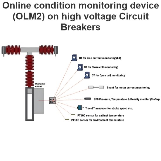
Online condition monitoring device (OLM2) on high voltage Circuit Breakers
This device is capable of monitoring and detecting various parameters according to the specifications outlined:SF6 Gas Monitoring:Utilizes a specialized sensor for measuring SF6 gas density.Capabilities include measuring gas temperature, monitoring SF6 leak rates, and calculating the optimal date for refilling.Mechanical Operation Analysis:Measures operational times for closing and opening cycles.Evaluates primary contacts separation speed, damping, and contact overtravel.Identifies signs of mec
Edwiin
02/13/2025
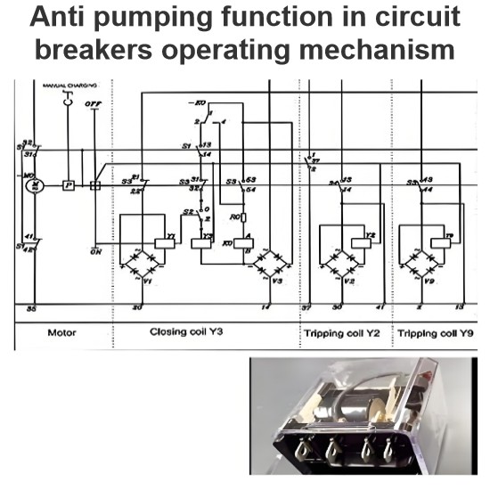
Anti pumping function in circuit breakers operating mechanism
The anti - pumping function stands as a crucial characteristic of control circuits. In the absence of this anti - pumping function, assume that a user connects a maintained contact within the closing circuit. When the circuit breaker is closed onto a fault current, the protective relays will promptly trigger a tripping action. However, the maintained contact in the closing circuit will attempt to close the breaker (once again) onto the fault. This repetitive and dangerous process is referred to
Edwiin
02/12/2025
Ageing phenomena of current pass blades in high voltage disconnector switch
This failure mode has three primary origins:Electrical Causes: The switching of currents, such as loop currents, can lead to localized wear. At higher currents, an electric arc may burn at a specific spot, increasing the local resistance. As more switching operations occur, the contact surface wears down further, causing an increase in resistance.Mechanical Causes: Vibrations, often due to wind, are the main contributors to mechanical aging. These vibrations cause abrasion over time, leading to
Edwiin
02/11/2025
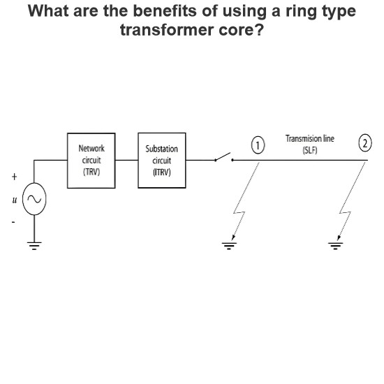
Initial Transient Recovery Voltage (ITRV) for high voltage circuit breakers
Transient Recovery Voltage (TRV) stress similar to that encountered during a short-line fault can also occur due to the busbar connections on the supply side of a circuit breaker. This specific TRV stress is known as Initial Transient Recovery Voltage (ITRV). Given the relatively short distances involved, the time to reach the first peak of ITRV is typically less than 1 microsecond. The surge impedance of the busbars within a substation is generally lower compared to that of overhead lines.The f
Edwiin
02/08/2025
Inquiry
Download
IEE-Business is dedicated to serving the personnel in the global power industry.
Join IEE-Business, not only can you discover power equipment and power knowledge, but also canhnd like - minded friends!