Energisation of back to back(b to b) cables by circuit breaker according to IEC

Edwiin
01/22/2025

The energization of a cable by the closing of a circuit breaker (CB) indeed results in a transient inrush current. The characteristics of this inrush current are influenced by several factors within the electrical system. Here is a refined and detailed explanation:

Factors Influencing Inrush CurrentApplied Voltage: The voltage level at the moment the CB closes directly affects the magnitude of the inrush current. Higher voltages can lead to higher initial current peaks.
Cable Surge Impedance: This is the characteristic impedance of the cable, which plays a significant role in determining how the transient currents behave. It limits the surge currents that occur during switching events.

Cable Capacitive Reactance: Cables have inherent capacitance, especially long or high-voltage cables. When energized, these capacitances charge up, causing an inrush current. The capacitive reactance influences both the magnitude and duration of this charging current.

Inductance in the Circuit: Inductive elements in the circuit affect the rate of change of the current. They oppose changes in current, thus influencing the shape and decay rate of the transient current waveform.
Charges on the Cable: Any residual charges present on the cable at the instant of closing can significantly impact the transient behavior. If the cable was previously energized and has not fully discharged, it can contribute to the inrush current.

Damping of the Circuit: Damping elements reduce oscillations and help to stabilize the system more quickly after a switching event. High damping can limit the peak and duration of the inrush current.

Back-to-Back Cable Switching

  • When cables are switched back-to-back (b-to-b), meaning one cable is de-energized while another is energized using the same switchgear, transient currents of high magnitude and rapid rate of change may flow between the cables. These currents are primarily due to the transfer of energy stored in the capacitance of the de-energized cable to the energized one.
  • Transient Current Characteristics: The surge current resulting from b-to-b switching is limited by the cable surge impedances and any series inductance present between the energized and switched cables. Typically, this transient decays rapidly, often within a fraction of a cycle of the system frequency.
  • Source Contribution: During such switching, the component of current supplied by the power source is minimal and changes slowly enough that it can generally be disregarded in the analysis of the transient phenomena.
  • Impact on Modern CBs: Due to the very high damping effect on the inrush current, switching parallel cables in modern systems typically does not pose a challenge for contemporary circuit breakers, which are designed to handle such transient conditions effectively.

Typical Circuit for B-to-B Cable Switching

A typical circuit for b-to-b cable switching would involve two sets of cables connected to a common point via a circuit breaker. Upon switching, as one set of cables becomes de-energized and the other energized, the transient currents flow through the circuit breaker and between the cables. The circuit design should take into account the factors mentioned above to ensure safe operation and minimize potential stresses on the equipment.

Unfortunately, I cannot provide or display a figure here, but you can visualize or find diagrams in technical literature or manuals related to power system engineering that depict such circuits. These resources will show the arrangement of cables, circuit breakers, and possibly other protective devices involved in b-to-b switching operations.

Edwiin

Hello,I'm Wdwiin. A decade of hands-on experience in electrical engineering, specializing in high-voltage systems, smart grids, and renewable energy technologies. Passionate about technical exchange and knowledge sharing, committed to interpreting industry trends with professional insights to empower peers. Connection creates value—let’s explore the boundless possibilities of the electrical world together!

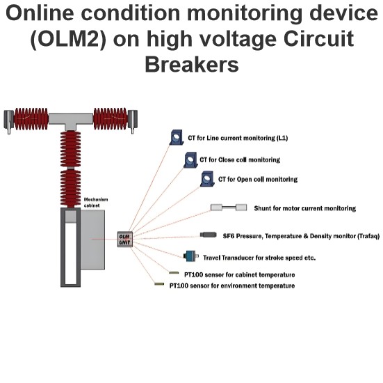
Online condition monitoring device (OLM2) on high voltage Circuit Breakers
This device is capable of monitoring and detecting various parameters according to the specifications outlined:SF6 Gas Monitoring:Utilizes a specialized sensor for measuring SF6 gas density.Capabilities include measuring gas temperature, monitoring SF6 leak rates, and calculating the optimal date for refilling.Mechanical Operation Analysis:Measures operational times for closing and opening cycles.Evaluates primary contacts separation speed, damping, and contact overtravel.Identifies signs of mec
Edwiin
02/13/2025
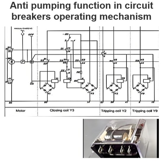
Anti pumping function in circuit breakers operating mechanism
The anti - pumping function stands as a crucial characteristic of control circuits. In the absence of this anti - pumping function, assume that a user connects a maintained contact within the closing circuit. When the circuit breaker is closed onto a fault current, the protective relays will promptly trigger a tripping action. However, the maintained contact in the closing circuit will attempt to close the breaker (once again) onto the fault. This repetitive and dangerous process is referred to
Edwiin
02/12/2025
Ageing phenomena of current pass blades in high voltage disconnector switch
This failure mode has three primary origins:Electrical Causes: The switching of currents, such as loop currents, can lead to localized wear. At higher currents, an electric arc may burn at a specific spot, increasing the local resistance. As more switching operations occur, the contact surface wears down further, causing an increase in resistance.Mechanical Causes: Vibrations, often due to wind, are the main contributors to mechanical aging. These vibrations cause abrasion over time, leading to
Edwiin
02/11/2025
Initial Transient Recovery Voltage (ITRV) for high voltage circuit breakers
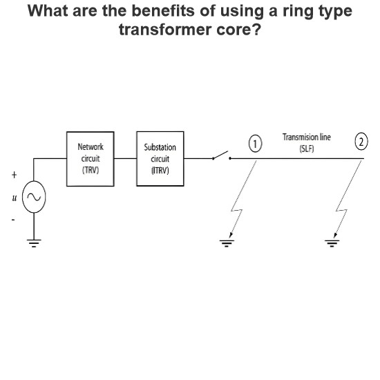
Transient Recovery Voltage (TRV) stress similar to that encountered during a short-line fault can also occur due to the busbar connections on the supply side of a circuit breaker. This specific TRV stress is known as Initial Transient Recovery Voltage (ITRV). Given the relatively short distances involved, the time to reach the first peak of ITRV is typically less than 1 microsecond. The surge impedance of the busbars within a substation is generally lower compared to that of overhead lines.The f
Edwiin
02/08/2025
Inquiry
Download
IEE-Business is dedicated to serving the personnel in the global power industry.
Join IEE-Business, not only can you discover power equipment and power knowledge, but also canhnd like - minded friends!