Traditional power transformers face inherent issues due to their sensors. Critically, they are vital for power plant monitoring, control, and protection (e.g., fault recording, safety control). However, large electrical energy transmission via information carriers and the lack of digital signal output from digital systems complicate secondary communication. Complex secondary wiring compensates for microcomputers’ high reliability, streamlining protection and secondary devices. This innovation will integrate secondary equipment into systems, accelerating substation digitization/computerization and transforming power system automation/protection.
Electronic transformers handle optical transmission isolation, yet high - voltage lines for signal recording/transmission need stable, reliable DC power—a key technical challenge rooted in physics. A variable electromagnetic field around the measured high - voltage conductor, obtainable via electromagnetic induction, is ideal (energy is “self - stimulating,” extracted from and used for the measured object, based on AC electromagnetic stimulation). Still, technical hurdles force reliance on costly methods (e.g., lasers, microwaves). This paper explores power supply self - regulation via cutting - edge electronic tech, covering optical communication and magnetic materials.
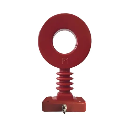
1 Air - core Coil
In this stage, high - voltage ETA uses air - core coils as sensing elements. Low - voltage semiconductor lasers, powered by optical fibers on high - voltage modulated lines, convert voltage signals. Measured electrical info (input as digital signals) drives LEDs, with optical fibers transmitting signals to the low - voltage side as optical pulses.
Unlike traditional transformer winding, air - core coils follow strict rules: Secondary windings are evenly distributed on non - metallic magnetic skeletons (uniform cross - section); coils share the same shape; each winding’s horizontal plane must align perpendicularly with the coil shell’s tangent (otherwise, measurement errors increase). Semi - manual winding often fails these criteria in practice, raising power consumption during mass production. Typically, air - core coil structural accuracy peaks at 0.1% (average 2%).
While temperature - related operation is simple, IEC standards mandate clear quantitative requirements for secondary output under rated current—all initial deviations count toward measurement errors. Solving air - core transformer atomization in production is crucial. Transformers with resistance labels need special approval (from the Electrical and Mechanical Services Department) for secondary output, hindering industrialization. Thus, new air - core coil optical sensor structures are needed. Via PCB tech, researchers developed innovative designs, boosting measurement accuracy and stability.
2 Transient Characteristics
In high - voltage grids, large system capacity leads to a constant, relatively long primary cycle. Relay protection activates during transitions, with long - duration short - circuit currents. To ensure protection device operation, transformers must stay slightly distorted; the second output signal replaces the first interrupt current, and transient defects within set time must not exceed limits. The transient performance of air - core coil - based electronic power transformers is a key strength.
An integrator, with a limited time constant, recovers measured electrical signals. If circuits have iodine - periodic components, error characteristics depend more on low - end frequencies. Lower down - frequencies improve tracking and reduce errors (e.g., a system’s opening element weakening in 0.5s requires the power converter’s low - frequency to stay below 2Hz for better damping cycle tracking). Slower transient decay and output signal attenuation occur when air - core current transformers and integrators shut off at zero primary current. Incompatibility with zero - position shutdown systems causes measurement errors. Thus, integrator design and optimization are critical for air - core transformer performance.
3 High - Voltage Side Power Supply
Air - core power transformers use “energy - taking power supplies” to draw energy from the primary conductor at high voltage. Electronic circuits provide power, but very low primary currents (e.g., ≤5% rated current) prevent current converters from maintaining normal excitation or transmitting energy, creating a power dead zone. Designing fiber - optic power for low - side semiconductor lasers’ high - voltage modulation circuits faces high power consumption (≈60mW).
Balancing energy use and performance is key: with 30% photoelectric conversion efficiency, semiconductor lasers need at least 180mW output—shortening their lifespan and raising costs. Hybrid energy carriers solve this: KT supplies power for high primary currents; laser - based supplies extend lifespans for low currents. Reliance on lasers risks transformer failure if they stop, so two optical modulators and smart control strategies (to predict mode switching and handle short - circuits) are needed, adding cost but ensuring reliable power.
4 Reliability Design
Electronic dampers outperform traditional ones but rely on complex technologies (e.g., tech transfer, high - voltage expertise), eventually replacing them. Redundancy boosts reliability: protection channels use dual - redundant air - core coils and converters. Key tools (e.g., power module converters) need simple automation. Protective measures address short - circuit impacts on sampling cycles and high - performance lasers in ATM protection channels. High - performance lasers pose operator risks but shut off with power modules to prevent hazards.