1 Performance Advantages
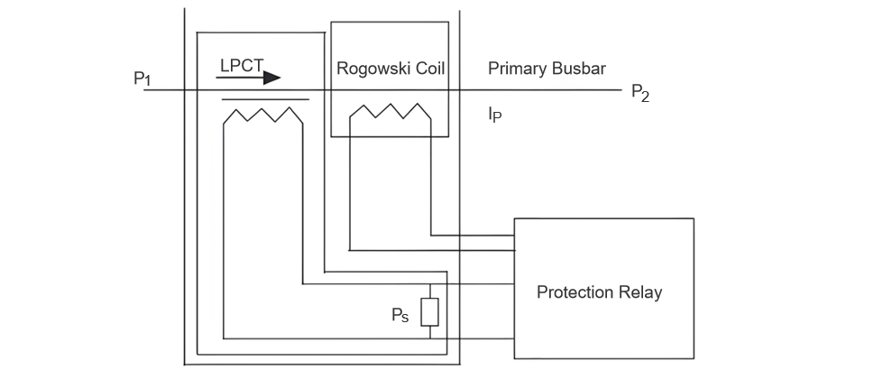
In recent years, electronic current transformers (ECTs) have emerged as a key industry trend. National standards classify them into two types: Active Optical Current Transformers (AOCTs, active hybrid type) and Optical Current Transformers (OCTs, passive optical type). Active hybrid ECTs use low-power electromagnetic transformers and Rogowski coils as core sensing elements (Figure 1).
Rogowski coils outperform traditional sensors with non-saturation and wide dynamic ranges, boosting current transmission efficiency. However, they suffer from low anti-interference capabilities (vulnerable to external magnetic fields, temperature/humidity changes) and error risks in manual/multi-layer winding. Among electromagnetic ECTs, low-power models stand out: mature technology, stable performance, high sensitivity, mass production readiness, and wide power system adoption.
2 Structure & Working Principle
2.1 LPCT: Structure & Operation
LPCT (a low-power electromagnetic ECT) is defined in GB/T 20840.8—2007 as an ECT implementation. As a representative electromagnetic transformer, LPCT’s performance and tech maturity grow yearly, promising broad applications.
LPCT benefits power systems with low secondary loads and relaxed measurement requirements. Using high-permeability materials (e.g., iron-based nanocrystalline alloys), it achieves accurate measurements with small cores.
Composed of a sampling resistor Rs, electromagnetic transformer, and signal transmission unit, LPCT operates as: Primary bus current converts to a secondary current, which the sampling resistor transforms into a voltage signal proportional to the primary current. A double-shielded twisted-wire transmission unit sends this signal to an Intelligent Electronic Device (IED), shielding external electromagnetic interference during transmission.
2.2 Structure and Working Principle of Rogowski Coils
Rogowski coils outperform other AC current measurement methods with advantages like excellent linearity, wide frequency bands, no iron core, low cost, light weight, and easy installation/maintenance. Crucially, they avoid hysteresis and saturation, ensuring broad, accurate measurements.
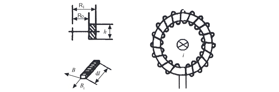
Commonly, soft wires are tightly wound around non-magnetic skeletons (see Figure 2) to form coils. Based on Ampère’s law, the integral of magnetic field strength H along a closed contour equals the enclosed current. However, precise, uniform winding (for consistent cross-sections) is hard to achieve in practice, limiting stability.
To address this, optimize coils for system needs. For example, use PCB - based designs with computer/IT tools for uniform wire layout and digital cross - section processing. Reverse - series winding of two coils can reduce electromagnetic interference, boosting voltage output and accuracy by canceling longitudinal magnetic fields.
Improved PCB Rogowski coils overcome traditional flaws (e.g., poor anti - interference, inaccurate measurements). With simpler structures, scientific designs, and precise manufacturing, they are ideal for power system promotion.
3 Testing Temperature Coefficients of Sampling Resistance & Rogowski Coil Internal Resistance
3.1 LPCT Sampling Resistance Temperature Coefficient Test
In practice, inconsistent material properties/processes cause resistance value deviations, affecting measurement accuracy. Resistance also changes with temperature, significantly impacting current transformer ratio errors.
Conclusion: PCB Rogowski coil and LPCT sampling resistance values vary with temperature, posing safety risks to power systems. Thus, scientifically test temperature impacts on PCB Rogowski coils and screen sampling resistors to ensure transformers meet design/operational stability needs.
3.2 Rogowski Coil Resistance Drift & Ratio Error Test
Operators simulate temperature environments, run PCB Rogowski coils under varied temperatures, record data changes, analyze temperature effects, and optimize designs to improve efficiency.
This test assesses PCB Rogowski coil performance/suitability for power systems. Using a constant - temperature chamber and LCR tester: place the coil in the chamber, then use LCR/electronic current test systems to measure resistance drift and ratio error, ensuring valid data via controlled temperature conditions (e.g., -50 °C, 250 °C, 450 °C).
Post - test analysis: PCB internal resistance is temperature - sensitive, but temperature minimally affects angular/ratio errors—ensuring power system protection.
4 Conclusion
Current transformers are critical for power system protection/measurement. Their performance directly impacts system stability and user electricity supply. Thus, enhance research on 10 kV electronic current transformers to support China’s power industry’s healthy growth.