• Product
  • Suppliers
  • Manufacturers
  • Solutions
  • Free tools
  • Knowledges
  • Experts
  • Communities
Search


What should be paid attention to in the design of low-voltage pole-mounted circuit breakers?

Dyson
Field: Electrical Standards
China

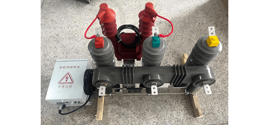
Low-voltage pole-mounted circuit breakers are critical protective and control devices in power systems, whose design and operation directly affect system safety and reliability. Their design must comprehensively address environmental adaptability, electrical parameter coordination, and actuator selection to ensure stable operation under diverse conditions. During operation, strict adherence to safety protocols, regular maintenance, and proper handling of exceptional situations are essential to prevent accidents caused by misoperation. This article systematically outlines key design principles and operational standards for low-voltage pole-mounted circuit breakers, providing professional guidance for engineering personnel.

1. Design Considerations for Low-Voltage Pole-Mounted Circuit Breakers

The design of low-voltage pole-mounted circuit breakers must withstand harsh outdoor environments while fulfilling protection and control requirements.

1.1 Environmental Adaptability

As outdoor-installed equipment, these breakers must endure temperature fluctuations, humidity, salt fog corrosion, and mechanical vibration. Per GB/T 2423.17, they must pass a 72-hour neutral salt spray test (Grade 5), suitable for coastal or industrial areas, with Pollution Degree 3 to resist conductive pollution or condensation. For high altitudes (>2000m), insulation and temperature rise parameters must be adjusted per GB/T 20645-2021 (temperature rise limit decreases by 1% per 100m increase; current rating reduction required above 4000m).

For low temperatures, operation at -40°C and storage at -55°C must be ensured, with reliable actuator performance. UV resistance requires surface coatings such as polyamide paint (contact angle >90°) or PVDF (UV aging resistance ≥ Grade 8). Enclosure sealing must meet IP54/55 standards to prevent insulation degradation.

1.2 Electrical Parameter Coordination

Accurate short-circuit current calculation and proper parameter selection are crucial. Short-circuit currents should be calculated using the absolute method, considering three-phase, two-phase, and single-phase ground fault currents. The initial three-phase short-circuit current is calculated as:

where Un is the nominal line voltage, and Rk, Xk are total resistance and reactance of the short-circuit loop. The breaker’s rated short-circuit breaking capacity (Ics) must not be less than the maximum three-phase short-circuit current. Sensitivity verification requires the minimum short-circuit current at the line end to be at least 1.3 times the instantaneous or short-time overcurrent trip setting: Imin≥1.3Iset3.

For overload protection, the long-time trip setting Iset1 must satisfy Iz≥Iset1≥Ic, where Iz is the conductor’s continuous current-carrying capacity and Ic is the calculated load current. For short-circuit protection, the instantaneous trip setting Iset3 should be ≥1.2 times the full starting current of the largest motor (e.g., 20–35 times rated current for squirrel-cage motors), while the short-time setting Iset2 should avoid transient load peaks, typically set at 1.2 times (maximum motor starting current + other load currents).

1.3 Actuator Selection

Spring-operated mechanisms are commonly used, requiring reliability, anti-jump, free-tripping, and buffering functions. Timing parameters: frame breakers—closing ≤0.2s, opening ≤0.1s; molded-case breakers—mechanical life ≥10,000 operations (frame breakers ≥20,000). The actuator must include energy storage detection and interlocking for safe operation. Dynamic characteristics require optimized contact speed and displacement control (e.g., staged control for vacuum breakers to minimize contact bounce). Output characteristics must match the breaker to ensure closure under short-circuit conditions. In cold regions, capacitor ESR increases at -40°C, prolonging closing time; variable-temperature testing is essential.

2. Protection Function Design and Setting Selection

2.1 Overload Protection

Typically implemented via thermal-magnetic or electronic trip units. Thermal-magnetic units use bimetallic strips with inverse-time characteristics (trip time inversely proportional to the square of overload current). Electronic units offer precise control, with long-time trip settings Ir ranging from 0.4 to 1 times the rated current In. Settings must satisfy In≥Ic and In≤Iz. Sensitivity: Sp=Ikmin/Iop≥1.3, where Ikmin is the minimum single-phase short-circuit current at the line end. For critical loads, overload protection may trigger alarms instead of tripping.

2.2 Short-Circuit Protection

Includes short-time and instantaneous protection. Short-time protection ensures selectivity: Iset2≥1.2 (max motor starting current + other loads), with time delays (0.1–0.4s) coordinated with upstream breakers (≥0.1–0.2s time difference). Instantaneous protection targets severe faults: Iset3≥1.2 full motor starting current (e.g., 12–18 times In for motors). For distribution feeders, electronic trip units with delayed instantaneous protection are preferred. Selectivity: upstream short-time setting ≥1.3 × downstream instantaneous setting, with ≥0.1–0.2s time delay difference.

2.3 Undervoltage Protection

Prevents equipment damage from voltage sags. Trip range: 35%–70% of rated voltage. Instantaneous types trip immediately but may cause nuisance tripping; delayed types (0–5s) ignore transient fluctuations, suitable for industrial use. The undervoltage trip unit’s rated voltage must match the line voltage, and its function must not interfere with other protections. Delayed types (0.2–3s) are recommended for industrial applications.

3. Selectivity Coordination and Cascading Protection

3.1 Selectivity Zones

  • Zone 1 (Isc < downstream Icu): Achieved via current and time grading (e.g., upstream Iset3&ge;1.2 downstream Iset3, time delay &ge; downstream + 0.1s).

  • Zone 2 (downstream Icu < Isc < upstream Icu): Relies on current-limiting characteristics or manufacturer data. Selectivity limit Is may be less than downstream Icu (partial selectivity).

  • Zone 3 (Isc > upstream Icu): Requires testing; upstream contacts may momentarily open (&le;30ms) without tripping, provided no welding occurs.

3.2 Cascading Protection

Leverages upstream breaker current-limiting to allow use of lower-breaking-capacity downstream breakers, reducing cost. Requires matching instantaneous settings and avoiding critical loads on cascaded circuits. Energy-based selectivity (e.g., in A-type breakers) can enhance selectivity limits, but verification via manufacturer data is essential.

3.3 Selectivity Methods

  • Current Selectivity: Upstream instantaneous setting &ge;1.3 &times; downstream.

  • Time Selectivity: Upstream short-time delay &ge; downstream + 0.1&ndash;0.2s.

  • Energy Selectivity: Based on contact system energy requirements.

  • Logic Selectivity: Downstream fault detection sends a lockout signal to upstream, enabling fast downstream tripping while upstream remains closed&mdash;ensuring "stable, accurate, fast" protection.

Give a tip and encourage the author!
Recommended
Key Technologies of Low-Voltage DC Solid-State Circuit Breakers
1 Technical Challenges1.1Stability of Device ParallelingIn practical applications, the current-carrying capacity of a single power electronic device is relatively limited. To meet high-current requirements, multiple devices are often connected in parallel. However, parameter variations between devices—such as slight differences in on-resistance and threshold voltage—can cause uneven current distribution during parallel operation. During switching transients, parasitic inductance and capacitance
Dyson
09/02/2025
Bridge-Type Fault Current Limiter | Superconducting & Solid-State
1 Bridge-Type Superconducting Fault Current Limiter1.1 Structure and Operating Principle of the Bridge-Type SFCLFigure 1 shows the single-phase circuit diagram of the bridge-type SFCL, which consists of four diodes D₁ to D₄, a DC bias voltage source V_b, and a superconducting coil L. A circuit breaker CB is connected in series with the limiter to interrupt the fault current after it has been limited. The bias source V_b provides a bias current i_b to the superconducting coil L. The voltage of V_
Dyson
08/25/2025
Operational Safety Procedures and Maintenance Requirements for Low-Voltage Pole-Mounted Circuit Breakers
Safe operation and regular maintenance of low-voltage pole-mounted circuit breakers are essential for long-term system reliability.1. Operational Safety ProceduresOperations must be strictly regulated under dispatch control, following the "Three Tickets and Two Systems" (work permit, operation ticket, emergency repair order; read-back and supervision systems). Operation tickets must use dual equipment identifiers (e.g., "XX kV XX Line XXX Circuit Breaker") and list detailed steps and safety meas
James
08/21/2025
Key Factors for Selecting Low-Voltage Circuit Breakers: Current Rating, Trip Characteristics & Environmental Adaptability
In the selection process of low-voltage circuit breakers, the following critical factors must be considered:Rated Current and Short-Circuit Breaking Capacity are fundamental to proper selection. According to relevant standards, the rated current of a circuit breaker should be equal to or greater than the calculated load current, with an additional safety margin (typically 1.1 to 1.25 times). Meanwhile, the short-circuit breaking capacity must exceed the maximum prospective short-circuit current
James
08/21/2025
Seed Inquiry
Download
Get the IEE Business Application
Use the IEE-Business app to find equipment, obtain solutions, connect with experts, and participate in industry collaboration anytime, anywhere—fully supporting the development of your power projects and business.