Armature Reaction in Alternators

Encyclopedia
08/19/2024

Armature Reaction Definition

Armature reaction in an alternator is defined as the effect of the armature’s magnetic field on the main magnetic field of the alternator or synchronous generator.

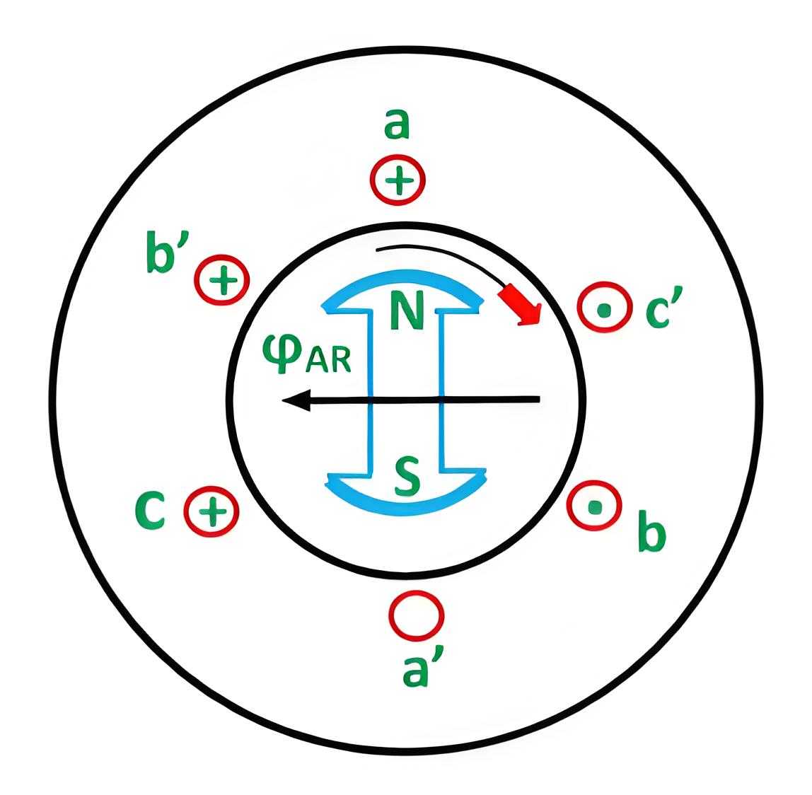
8bc6e6c8d55ff075ee81595c59e65da3.jpeg

 Magnetic Field Interaction

When the armature carries current, its magnetic field interacts with the main field, causing either distortion (cross-magnetizing) or reduction (demagnetizing) of the main field flux.

Power Factor Influence

At unity power factor, the angle between armature current I and induced emf E, is zero. That means, armature current and induced emf are in same phase. But we know theoretically that emf induced in the armature is due to changing main field flux, linked with the armature conductor.

As the field is excited by DC, the main field flux is constant in respect to field magnets, but it would be alternating in respect of armature as there is a relative motion between field and armature in the alternator. If main field flux of the alternator in respect of armature can be represented as

Then induced emf E across the armature is proportional to, dφf/dt.

c019e1efa19f41ea6921bc30b20dede0.jpeg 

Hence, from these above equations (1) and (2) it is clear that the angle between, φf and induced emf E will be 90o.

b788cc912e6cdf9dce8fb47fec514776.jpeg

Now, armature flux φa is proportional to armature current I. Hence, armature flux φa is in phase with armature current I.

Again at unity electrical power factor I and E are in same phase. So, at unity power factor, φa is phase with E. So at this condition, armature flux is in phase with induced emf E and field flux is in quadrature with E. Hence, armature flux φa is in quadrature with main field flux φf.

As this two fluxes are perpendicular to each other, the armature reaction of the alternator at unity power factor is purely distorting or cross-magnetising type.

As the armature flux pushes the main field flux perpendicularly, distribution of main field flux under a pole face does not remain uniformly distributed. The flux density under the trailing pole tips increases somewhat while under the leading pole tips it decreases.

Lagging and Leading Loads

At leading power factor condition, armature current “I” leads induced emf E by an angle 90o. Again, we have shown just, field flux φf leads, induced emf E by 90o.

Again, armature flux φa is proportional to armature current I. Hence, φa is in phase with I. Hence, armature flux φa also leads E, by 90o as I leads E by 90o.

As in this case both armature flux and field flux lead, induced emf E by 90o, it can be said, field flux and armature flux are in the same direction. Hence, the resultant flux is simply arithmetic sum of field flux and armature flux. Hence, at last, it can be said that armature reaction of alternator due to a purely leading electrical power factor is the magnetizing type.

Unity Power Factor Effect

  • The armature reaction flux is constant in magnitude and rotates at synchronous speed.

  • The armature reaction is cross magnetising when the generator supplies a load at unity power factor.

  • When the generator supplies a load at leading power factor the armature reaction is partly demagnetising and partly cross-magnetising.

  • When the generator supplies a load at leading power factor the armature reaction is partly magnetising and partly cross-magnetising.

  • Armature flux acts independently of main field flux.

Encyclopedia

The Electricity Encyclopedia is dedicated to accelerating the dissemination and application of electricity knowledge and adding impetus to the development and innovation of the electricity industry.

Cost Differences and Performance Comparison of 35kV New Energy Transformers Based on Dry-Type, Mineral Oil, and Vegetable Oil
For users, when purchasing a 35kV new energy transformer, choosing between dry-type, mineral oil-filled, or vegetable oil-filled types involves multiple considerations. These include user habits, maintenance-free performance, safety and fire resistance, volume and weight, among others. However, cost differences are undoubtedly one of the most crucial factors.To illustrate the issue intuitively, this paper selects a three-level energy efficiency dual-winding new energy transformer with a rated ca
Ron
07/26/2025
What is the connection group of a transformer?
Transformer Connection GroupThe connection group of a transformer refers to the phase difference between the primary and secondary voltages or currents. It is determined by the winding directions of the primary and secondary coils, the labeling of their start and end terminals, and the connection mode. Expressed in a clock-like format, there are 12 groups in total, numbered from 0 to 11.The DC method is commonly used to measure the transformer's connection group, mainly to verify whether the con
Vziman
07/26/2025
What is the sequence for powering down the transformer?
The sequence for shutting down a main transformer is as follows: when de-energizing, the load side should be shut down first, followed by the power supply side. For energizing operations, the reverse order applies: the power supply side is energized first, then the load side. This is because: Energizing from the power supply side to the load side makes it easier to identify the fault range and take prompt judgment and handling measures in case of a fault, preventing the fault from spreading or e
Rockwell
07/26/2025
What are the methods for switching operations of station transformers?
Let's take an auxiliary power system with two station transformers as an example. When one station transformer needs to be out of service, there are two operation methods: non-interruptive power supply and instantaneous power interruption. Generally, the method of instantaneous power interruption on the low-voltage side is preferred.The operation method for instantaneous power interruption on the low-voltage side is as follows:Open the 380V power incoming circuit breaker of the corresponding sec
Vziman
07/26/2025
Inquiry
Download
IEE-Business is dedicated to serving the personnel in the global power industry.
Join IEE-Business, not only can you discover power equipment and power knowledge, but also canhnd like - minded friends!