Stator Voltage Control of an Induction Motor

Edwiin
05/23/2025

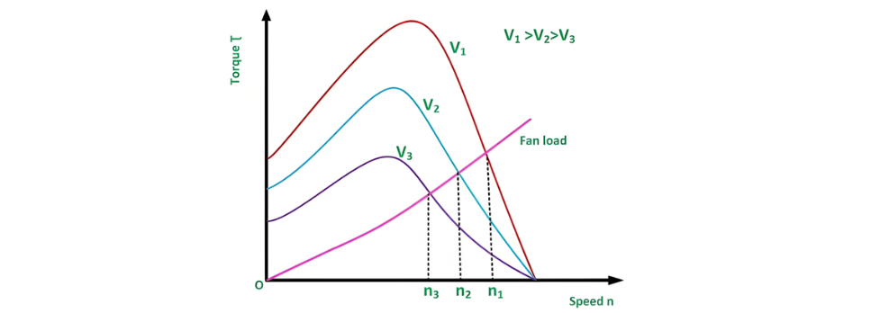
Stator voltage control represents a method employed to regulate the speed of an induction motor. The rotational speed of a three-phase induction motor can be adjusted by varying the supply voltage. As is well established, the torque generated by the motor is proportional to the square of the supply voltage, while the slip at the point of maximum torque remains independent of the supply voltage. Notably, fluctuations in the supply voltage do not affect the synchronous speed of the motor.
The torque-speed characteristics of three-phase induction motors under different supply voltages, along with the characteristics for a fan load, are illustrated below:
Stator voltage control is a technique used to regulate the speed of an induction motor. The rotational speed of a three-phase induction motor can be adjusted by varying the supply voltage. The torque generated by the motor is proportional to the square of the supply voltage, while the current is directly proportional to the voltage. Thus, the speed is controlled by adjusting the voltage until the motor develops the torque required by the load at the desired speed.
To reduce the speed while maintaining the same current, the voltage is decreased, which in turn reduces the torque output. This stator voltage control method is particularly suitable for applications where the load torque decreases with speed, such as fan loads.
This approach allows speed control only below the normal rated speed, as operating at voltages higher than the rated value is not permissible. It is ideal for drives requiring intermittent operation, as well as fan and pump systems, where the load torque varies with the square of the speed. These drives demand lower torque at lower speeds, a condition that can be met by applying a lower voltage without exceeding the motor's current rating.
For speed control of small-sized motors (primarily single-phase), variable voltage can be achieved through the following methods:
  • Connecting an external resistance in the motor's stator circuit.
  • Using an auto-transformer.
  • Employing a thyristor voltage controller.
  • Utilizing a triac controller.
The thyristor voltage controller method is now the preferred choice for voltage variation. For a single-phase supply, two thyristors are connected back-to-back, as illustrated in the figure below:
The domestic fan motors, which are single-phase are controlled by a single-phase Triac Voltage Controller as shown in the figure below:
Speed control is achieved by adjusting the firing angle of the Triac. These controllers are commonly referred to as solid-state fan regulators. Compared to conventional variable regulators, solid-state regulators offer greater compactness and efficiency, making them the preferred choice over traditional regulators.
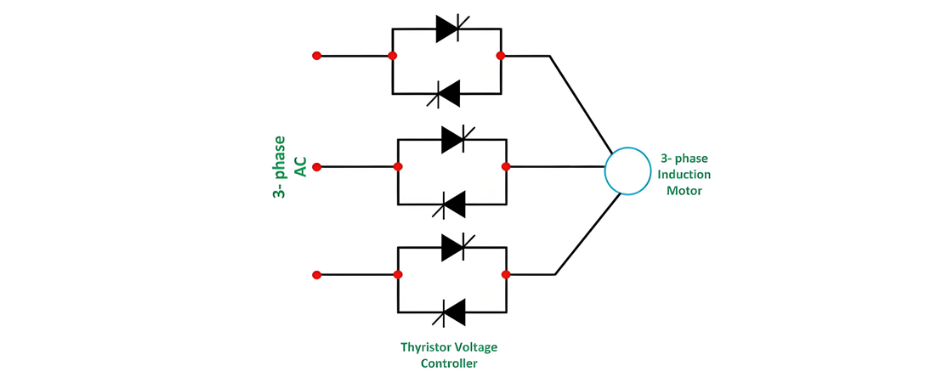
For a three-phase induction motor, three pairs of thyristors are required, with each pair consisting of two thyristors connected back-to-back. The diagram below illustrates the stator voltage control of three-phase induction motors using a thyristor voltage controller:
Each pair of thyristors controls the voltage of the corresponding phase. Speed regulation is achieved by adjusting the conduction period of the thyristors. For lower power ratings, the back-to-back thyristor pairs in each phase can be replaced by a Triac.
Edwiin

Hello,I'm Wdwiin. A decade of hands-on experience in electrical engineering, specializing in high-voltage systems, smart grids, and renewable energy technologies. Passionate about technical exchange and knowledge sharing, committed to interpreting industry trends with professional insights to empower peers. Connection creates value—let’s explore the boundless possibilities of the electrical world together!

Cost Differences and Performance Comparison of 35kV New Energy Transformers Based on Dry-Type, Mineral Oil, and Vegetable Oil
For users, when purchasing a 35kV new energy transformer, choosing between dry-type, mineral oil-filled, or vegetable oil-filled types involves multiple considerations. These include user habits, maintenance-free performance, safety and fire resistance, volume and weight, among others. However, cost differences are undoubtedly one of the most crucial factors.To illustrate the issue intuitively, this paper selects a three-level energy efficiency dual-winding new energy transformer with a rated ca
Ron
07/26/2025
What is the connection group of a transformer?
Transformer Connection GroupThe connection group of a transformer refers to the phase difference between the primary and secondary voltages or currents. It is determined by the winding directions of the primary and secondary coils, the labeling of their start and end terminals, and the connection mode. Expressed in a clock-like format, there are 12 groups in total, numbered from 0 to 11.The DC method is commonly used to measure the transformer's connection group, mainly to verify whether the con
Vziman
07/26/2025
What is the sequence for powering down the transformer?
The sequence for shutting down a main transformer is as follows: when de-energizing, the load side should be shut down first, followed by the power supply side. For energizing operations, the reverse order applies: the power supply side is energized first, then the load side. This is because: Energizing from the power supply side to the load side makes it easier to identify the fault range and take prompt judgment and handling measures in case of a fault, preventing the fault from spreading or e
Rockwell
07/26/2025
What are the methods for switching operations of station transformers?
Let's take an auxiliary power system with two station transformers as an example. When one station transformer needs to be out of service, there are two operation methods: non-interruptive power supply and instantaneous power interruption. Generally, the method of instantaneous power interruption on the low-voltage side is preferred.The operation method for instantaneous power interruption on the low-voltage side is as follows:Open the 380V power incoming circuit breaker of the corresponding sec
Vziman
07/26/2025
Inquiry
Download
IEE-Business is dedicated to serving the personnel in the global power industry.
Join IEE-Business, not only can you discover power equipment and power knowledge, but also canhnd like - minded friends!